3
Building Technologies
A6V10200368_b_--_--
Fire Safety
2012-05
en
Installation
Intended use
The SMF6120 radio base may only be used as a
replacement device in fire detection installations that
were installed prior to April 1, 2011!
When combined with manual call point SMF121
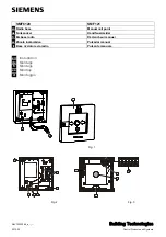
(Fig. 1, [1]), radio base SMF6120 (Fig. 1, [2]) is used to
manually trigger alarms in the event of fires. The manual
call point and a radio gateway (e.g. FDCW221) are
connected wirelessly.
Installation
Check whether the intended installation site is
within range of the radio gateway.
1.
Use appropriate screws to secure radio base
(Fig. 1, [2]) to a plane surface at a height of 1.3…1.6 m.
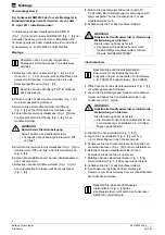
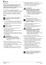
Use the mounting openings for this purpose (Fig. 2,
[3]).
Note the word 'TOP' on the radio base housing.
2.
Use a suitable key to open door of manual call point
(Fig. 1, [1]).
3.
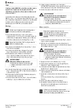
Break open opening (Fig. 3, [4]) on rear of manual call
point's housing.
4.
Guide two connection cables (Fig. 1, [5]) from radio
base through opening (Fig. 3, [4]) into manual call point.
WARNING
Incorrect terminal assignment
The manual call point does not work
•
Always use terminals 'b
▼
' and 'b
▲
'!
5.
Clip one connection cable (Fig. 1, [5]) to each of the
terminals 'b
▼
' and 'b
▲
' in the terminal strip (Fig. 3, [6]).
6.
Do not place the batteries in the radio base until you are
ready to commission it.
7.
Use screws supplied to secure manual call point
(Fig. 1, [1]) on radio base (Fig. 1, [2]).
8.
Stick the sign stating 'ATTENTION! Interruption of wire
results in alarm!' on the inside of the manual call point's
door.
9.
Close the manual call point's door.
DANGER
Deactivating the manual call points prevents
alarms from being forwarded.
Alarming does not take place.
•
Mark deactivated manual call points or those
which are not fully functional with the notice
'NOT IN USE'!
Commissioning
Also note the corresponding documents for
commissioning the radio cell and for the radio
gateway used, e.g. 'FDCW221 Radio gateway',
doc. 009865.
1.
Use a suitable key to open door of manual call point
(Fig. 1, [1]).
2.
Loosen retaining bolts in manual call point and lift
manual call point off radio base (Fig. 1, [2]).
WARNING
Deactivating the manual call points prevents
alarms from being forwarded.
Alarming does not take place.
•
The radio base will only function correctly if you
use 3.6 V lithium AA batteries!
3.
Press alarm pushbutton (Fig. 3, [12]).
4.
Place two 3.6 V lithium AA batteries (Fig. 2, [7]) in radio
base.
5.
Connect batteries' plug connections to the two bushes
(Fig. 2, [8]) on the PCB.
6.
Use screws to reconnect manual call point to radio
base.
7.
Actuate reset slider (Fig. 3, [13]).
The alarm pushbutton (Fig. 3, [12]) jumps out again.
8.
Close the manual call point's door.
9.
Register radio base as described in the document for
the radio gateway or for commissioning the radio cell.
Note that the LED display for the manual call
point's alarm indicator (Fig. 3, [10]) is not
supported by radio base SMF6120
.

