background image


SLI-5310/SLI-5310-I IAD


User’s Manual 


Rev: 1.3 

2007/03/30 

No part of this publication may be reproduced in any form by any means without the prior written permission. 

Other trademarks or brand names mentioned herein are trademarks or registered trademarks of their respective 

companies. 

i


Summary of Contents for SLI-5310

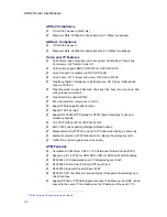
Page 1: ...1 3 2007 03 30 No part of this publication may be reproduced in any form by any means without the prior written permission Other trademarks or brand names mentioned herein are trademarks or registered trademarks of their respective companies i ...

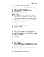
Page 2: ... or use of this document or the material contained herein S St ta at te em me en nt t o of f C Co on nd di it ti io on ns s In the interest of improving internal design operational function and or reliability the seller reserves the right to make changes to the products described in this document without notice The seller does not assume any liability that may occur due to the use or application o...

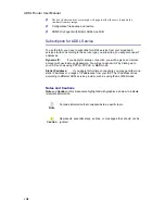
Page 3: ...s product from the wall outlet when it is not in use or before cleaning Pay attention to the temperature of the power adapter The temperature might be high After powering off the product power on the product at least 15 seconds later Do not block the ventilating openings of this product When the product is expected to be not in use for a period of time unplug the power cord of the product to preve...

Page 4: ...CC Rules These limits are designed to provide reasonable protection against harmful interference in a residential installation This equipment can generate use and radiate radio frequency energy and if not installed and used in accordance with the instructions may cause harmful interference to radio communications However there is no guarantee that interference will not occur in a particular instal...

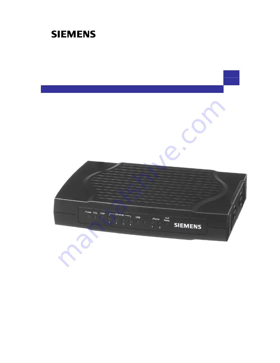
Page 5: ...r To benefit users access to the Internet 4 port 10 100 Mbps Ethernet switch hub is equipped with this IAD Also the feature rich routing functions are seamlessly integrated to ADSL service for existing corporate or home users Now users can enjoy various bandwidth consuming applications via the SLI 5310 SLI 5310 I IAD Unpacking Check the contents of the package against the pack contents checklist b...

Page 6: ...g Modem function Support T 38 Fax relay1 Support RFC2833 RTP Payload for DTMF Digits Telephony Tones and Telephony Signals Two VOIP FXS ports for VOIP phone calls Both VOIP ports supporting intelligent lifeline backup Manual selection of PSTN mode or VOIP mode while making a phone call Automatic selection of PSTN phone call on dialing the emergency calls Traffic flow control to guarantee voice qua...

Page 7: ...Static routes RFC1058 RIPv1 RFC1723 RIPv2 DNS Relay Dynamic DNS DHCP Client Relay Server Time protocol can be used to get current time from network time server Support IGMP Proxy Support port mapping function which allows you to assign all data traffic transmitted among specific Internet connections and LAN ports Support IP Bridge QoS for prioritize the transmission of different traffic classes Su...

Page 8: ...ll be given an Internet account with username and password You will get a dynamic IP by dialing up to your ISP such as using PPPoA PPPoE or MER mode Static IP address If you apply for full time connectivity you may get either one static IP address or a range of IP addresses from your ISP The IP address varies according to different ADSL service provider such as using IPoA or MER mode Notes and Cau...

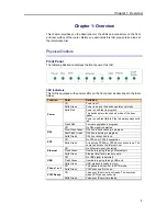
Page 9: ...always stays solid red Flash Red Firmware upgrades in progress Off No DSL signal is detected Slow Flash Green DSL line is handshaking in progress Fast Flash Green DSL line is training in progress DSL Solid Green DSL line connection is up Off No PPPoA or PPPoE connection PPP Solid Green At least one PPPoA or PPPoE connection is up The users can access the Internet now Off No Ethernet signal is dete...

Page 10: ...ctor Description Phone Phone set connector PSTN PSTN connector DSL RJ 11 connector Ethernet 1 4 Ethernet 10 100 Base T auto sensing USB USB connector for model with USB interface only Power Switch 12VAC Power connector Note For use only with power supply OEM type AA 121A5BN Leader type A48120150 C5 2 ...

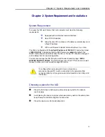
Page 11: ...ble to access the IAD or the host PC should be assigned an IP address first for initial configuration You also can manage the IAD through a web browser based manager ADSL ROUTER CONTROL PANEL The IAD manager uses the HTTP protocol via a web browser to allow you to set up and manage the device To configure the device via web browser at least one properly configured PC must be connected to the netwo...

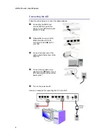
Page 12: ...utlet with RJ 11 cable o Please attach one end of the Ethernet cable with RJ 45 connector to the LAN port of your IAD p Connect the other end of the cable to the Ethernet port of the client PC q Connect the supplied power adapter to the PWR port of your IAD and plug the other end to a power outlet r Turn on the power switch Here is an example for connecting the PC to the IAD 4 ...

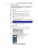
Page 13: ...mplete window of the InstallShield Wizard appears click Finish r Link your IAD and the PC with a USB cable s The system will detect the USB driver automatically Then the system will copy the proper files for this IAD Note If the USB device is not detected automatically check the USB cable between the PC and the device Besides verify that the device is power on t When the file copying finished the ...

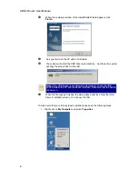
Page 14: ...he proper files for this IAD Note If the USB device is not detected automatically check the USB cable between the PC and the device Besides make sure that the device is power on t When the file copying finished the dialog above will close Now the USB driver is installed properly You can use the IAD To make sure that your IAD is properly installed please do the following steps 1 Right click on My C...

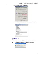
Page 15: ...click Device Manager 3 Confirm that the Siemens ADSL Router USB Remote NDIS Device is on the Network adapters list For Windows XP n Run the USB installation program from the CD provided in your IAD package o An InstallShield Wizard will appear Please wait for a moment 7 ...

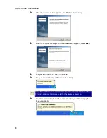
Page 16: ...rs click Finish r Link your IAD and the PC with a USB cable s The system will detect the USB driver automatically t Then the system will try to find the proper driver for your IAD and copy the files automatically Note If the USB device is not detected check the USB cable between the PC and the device Also make sure that the device is power on 8 ...

Page 17: ... the file copying finished a completing message will appear v You can use the IAD now To make sure your IAD is properly installed please do the following steps 1 Right click on My Computer and press Properties 2 On the Hardware tab click Device Manager 9 ...

Page 18: ...dow asking for permission to continue during USB driver installation process see the figure below for example To install the USB driver before connect the router to the PC here provides two methods Method One Use the driver CD came with the product package n Run the USB installation program on the CD provided in your router package o An InstallShield Wizard will appear Please wait for a moment 10 ...

Page 19: ...ion p When the welcome screen appears click Next for the next step q When the complete message of InstallShield Wizard appears click Finish r Link your router and the PC with a USB cable s The system will detect the USB driver automatically 11 ...

Page 20: ...te If the USB device is not detected check the USB cable between the PC and the device Also make sure that the device is power on t After the file copying finished a completing message will appear u You can use the router now 12 ...

Page 21: ...n Unplug the USB cable between your IAD and your PC Then click OK o Choose Settings Control Panel from the Start menu Choose Add Remove Programs p A dialog appears to ask you to choose the program that you want to remove Please select Siemens ADSL Router USB Driver and click Change Remove q The InstallShield Wizard dialog will appear r When the Maintenance Complete screen appears the USB driver is...

Page 22: ...band Uninstall Siemens ADSL Router USB Driver from the Start menu p The InstallShield Wizard dialog will appear q A dialog appears to confirm whether you want to remove the USB driver or not Please click Ok r When the Maintenance Complete screen appears the USB driver is removed successfully Click Finish 14 ...

Page 23: ...dware and left click on it 2 Click the dialog for Stop Siemens ADSL Router USB Remote NDIS Device 3 The Router is safely removed click OK to continue o Choose Settings Control Panel from the Start menu Choose Add Remove Programs p A dialog appears to ask you to choose the program that you want to remove Please select Siemens ADSL Router USB Driver and click Change Remove 15 ...

Page 24: ...l dialog will show up unplug your device from the USB port and click OK r The InstallShield Wizard will guide you till the USB driver is removed s When the Maintenance Complete screen appears the USB driver is removed successfully Click Finish 16 ...

Page 25: ...SL Router USB Driver from the Start menu p The InstallShield Wizard dialog will appear q A dialog appears to confirm whether you want to remove the USB driver or not Unplug the USB cable from your PC and click Ok r When the Maintenance Complete screen appears the USB driver is removed successfully Click Finish Method Two n Unplug your USB cable between your IAD and your PC o Choose Settings Contro...

Page 26: ...gram that you want to remove Please select Siemens ADSL Router USB Driver and click Change Remove q The InstallShield Wizard dialog will appear r A dialog appears to confirm whether you want to remove the USB driver or not Unplug the USB cable from your PC and click Ok 18 ...

Page 27: ... Vista For Vista users please press Continue whenever a prompted window asking for permission to continue during USB driver uninstallation process see the figure below for example To uninstall the USB driver there are two ways to do it Please follow the instructions Method One Remove from Device Manager n Choose Start menu and then select Control Panel 19 ...

Page 28: ...ADSL Router User Manual o Click System and Maintenance p Press System q Click Device Manager 20 ...

Page 29: ...t and press Uninstall s Click OK when the Confirm Uninstall window appears Remember to unplug the USB cable before continue the uninstallation or you will see the reminder as follows Unplug and press OK t When the Confirm Device Uninstall screen show up check Delete the driver software for the device and click OK to continue 21 ...

Page 30: ...appear Method Two uninstall from program list Note If your USB driver is installed by UPnP device you can only use method one via the Device Manager to uninstall because the installed driver will not be shown on the program list n Unplug your USB cable between your router and your PC o Choose Start menu and open Control Panel folder Click Uninstall a program 22 ...

Page 31: ...he list click Refresh button or F5 to update the information To remove the driver select it and then press Uninstall q Then the system will start to uninstall the USB driver software automatically Refresh button r When Maintenance Complete window shows up click Finish to exit 23 ...

Page 32: ...ADSL Router User Manual s The USB driver is successfully removed now 24 ...

Page 33: ...lease follow the steps below to set your network adapter If the TCP IP protocol has not been installed yet please follow the steps below for installation In the following illustrations we will set the PC to get an IP address automatically at the same time For Windows 98 1 Open the Start menu point to Settings and click on Control Panel 2 Double click the Network icon 25 ...

Page 34: ...dd Option 2 If you have TCP IP protocol skip to Step 6 4 Highlight Protocol and click Add 5 Highlight Microsoft on the left side of the window and select TCP IP on the right side Then click OK 6 When returning to the Network window highlight TCP IP protocol for your NIC and click Properties Your networ interface card Check out if for your NI installed or k TCP IP C is not 26 ...

Page 35: ...the IP Address tab Enable Obtain an IP address automatically and click OK 8 When returning to the Network window click OK 9 Wait for Windows when copying files 10 When prompted with System Settings Change dialog box click Yes to restart your computer 27 ...

Page 36: ... icon 3 The Network window appears On the Configuration tab check out the list of installed network components Option 1 If there is no TCP IP protocol click Add Option 2 If you have TCP IP protocol skip to Step 6 4 Highlight Protocol and click Add Your networ interface card Check out if for your NI installed or k TCP IP C is not 28 ...

Page 37: ...rosoft on the left side of the windows and select TCP IP on the right side Then click OK 6 While returning to Network window highlight TCP IP protocol for your NIC and click Properties 7 On IP Address tab Enable Obtain an IP address automatically and click OK 29 ...

Page 38: ...window click OK 9 Wait for Windows when copying files 10 When prompted with the System Settings Change dialog box click Yes to restart your computer For Windows NT 1 Click Start point to Settings and then click Control Panel 2 Double click the Network icon 30 ...

Page 39: ... out the list of installed network components Option 1 If there is no TCP IP Protocol click Add Option 2 If you have TCP IP Protocol installed skip to Step 7 4 Highlight TCP IP Protocol and click OK 5 Insert the Windows NT CD into your CD ROM drive and type the location of the CD Then click Continue 31 ...

Page 40: ...n returning to the Network window Open the Protocols tab then select TCP IP Protocol and click Properties 7 Enable Obtain an IP address from a DHCP server and click OK 8 When prompted with the message below click Yes to continue 32 ...

Page 41: ... 9 When returning to Network window click Close 10 When prompted with Network Settings Change dialog box click Yes to restart your computer For Windows 2000 1 From the Start menu point to Settings and then click Network and Dial up Connections 33 ...

Page 42: ...ection icon and then click Properties 3 On the General tab check out the list of installed network components Option 1 If there is no TCP IP Protocol click Install Option 2 If you have TCP IP Protocol skip to Step 6 4 Highlight Protocol and then click Add 34 ...

Page 43: ...ck Internet Protocol TCP IP and then click OK 6 When returning to the Local Area Connection Properties window highlight Internet Protocol TCP IP and then click Properties 7 Under the General tab enable Obtain an IP address automatically Then click OK 35 ...

Page 44: ...ADSL Router User Manual For Windows XP 1 Open the Start menu point to Control Panel and click it 2 Double click the Network Connection 3 Right click Local Area Connection and then click Properties 36 ...

Page 45: ...d network components Option 1 If there is no TCP IP Protocol click Install Option 2 If you have TCP IP Protocol skip to Step 7 5 Highlight Protocol and then click Add 6 Click Internet Protocol TCP IP and then click OK If th IP protocol installed on your PC press Install to continue ere is no TCP 37 ...

Page 46: ...e General Tab on the Local Area Connection Properties window highlight Internet Protocol TCP IP and then click Properties 8 Under the General tab select Obtain an IP address automatically and Obtain DNS server address automatically Then click Ok 38 ...

Page 47: ...Chapter 2 System Requirement and Installation For Windows Vista 9 Open the Start menu point to Control Panel and click it 10 Click Network and Internet 11 Select Network and Sharing Center 39 ...

Page 48: ...t click Local Area Connection and select Properties 14 On the Networking tab you will find Internet Protocol Version 6 and Version 4 Contact your ISP to confirm which one will be used We take TCP IPv4 for example here Select Internet Protocol Version 4 TCP IPv4 and press Properties 40 ...

Page 49: ...Chapter 2 System Requirement and Installation 15 Under the General tab select Obtain an IP address automatically and Obtain DNS server address automatically Then click Ok to exit 41 ...

Page 50: ... Internet To solve this problem please follow the procedures below to renew PC s IP address For Windows 98 ME 1 Select Run from the Start menu 2 Type winipcfg in the text box and click OK 3 When the figure below appears click Release to let go of the address and then click the Renew button to obtain a new IP address For Windows NT 2000 XP 1 Open the Start menu and click Run on this menu 42 ...

Page 51: ...nd prompt From Start menu point to Programs select Accessories and then click Command Prompt 3 Type ipconfig at the command prompt window and press Enter to view the computer s IP information from DHCP server 4 If the computer is holding a current IP address type ipconfig release to let go of the address then type ipconfig renew to obtain a new one Released IP Address 43 ...

Page 52: ...lick OK 2 The command prompt window will appear 3 Type ipconfig at the command window and press Enter to view the computer s IP information from DHCP server 4 If the computer is holding a current IP address type ipconfig release to let go of the address then type ipconfig renew to obtain a new one 44 ...

Page 53: ... and see the message The requested operation requires elevation please go to the Start menu and right click Command Prompt then set Run as administrator Press Continue when a dialog asking for permission to continue prompts After then repeat the above instruction to release and renew the IP address 45 ...

Page 54: ... over ATM IPoA NAT Unnumbered IP over ATM IPoA Unnumbered IP over ATM IPoA NAT Bridge Mode MER Bridge Mode NAT To ensure your PC accessing the Internet successfully please check the following first A network interface card is installed on your PC The IAD is solidly connected with your computer The TCP IP protocol has been installed and the IP address setting is to obtain IP address automatically W...

Page 55: ...nection Type page select PPP over ATM PPPoA then click the Next button 4 On the WAN IP Settings page select Obtain an IP address automatically and check Enable NAT box Click Next 5 On the PPP Username and Password page enter the PPP username and password that you got from your ISP Select Always on or select Dial on Demand and key in the inactivity timeout value The default value is 20 minutes Then...

Page 56: ...on Type page select PPP over Ethernet PPPoE then click the Next button 4 On the WAN IP Settings page select Obtain an IP address automatically and check Enable NAT box Click Next 5 On the PPP Username and Password page enter the PPP username and password that you got from your ISP Select Always on or select Dial on Demand and key in the inactivity timeout value The default value is 20 minutes Then...

Page 57: ...s 255 255 255 248 The WAN IP address is 10 3 95 233 and the subnet mask for WAN is 255 255 255 248 Configuration 1 Start your browser and type 192 168 1 1 in the URL box to access ADSL web based manager 2 Go to Quick Start Quick Setup Uncheck Auto Scan Internet Connection PVC Key in the VCI and VPI value e g VPI 0 VCI 32 Click the Next button 3 On the Configure Internet Connection Connection Type ...

Page 58: ...ck Next 7 Check the network information on the Summary page Make sure the settings match the settings provided by your ISP Click Finish 8 Refer to the TCP IP properties specify an IP Address and fill in other information needed e g IP Address 10 3 80 82 Subnet Mask 255 255 255 248 Gateway 10 3 80 81 Preferred DNS server 168 95 1 1 9 Now the IAD is well configured You can access the Internet 50 ...

Page 59: ...ed to PCs on the LAN The following example uses the IP address ranging from 10 3 80 81 to 10 3 80 86 and the subnet mask is 255 255 255 248 Configuration 1 Start your browser and type 192 168 1 1 in the URL box to access ADSL web based manager 2 Go to Quick Start Quick Setup Uncheck Auto Scan Internet Connection PVC Key in the VCI and VPI value e g VPI 0 VCI 32 Click the Next button 3 On the Confi...

Page 60: ...your LAN e g Primary IP Address 192 168 1 1 Subnet mask 255 255 255 0 Start IP Address 192 168 1 2 End IP Address 192 168 1 254 7 Check the network information Make sure the settings match the settings provided by ISP Click Finish 8 Now the IAD is well configured You can access into Internet 52 ...

Page 61: ...AN IP Configuration 1 Start your browser and type 192 168 1 1 in the URL box to access ADSL web based manager 2 Go to Quick Start Quick Setup Uncheck Auto Scan Internet Connection PVC Key in the VCI and VPI value e g VPI 0 VCI 32 Click the Next button 3 On the Configure Internet Connection Connection Type page select IP over ATM IPoA then click Next 4 On the WAN IP Settings page select None for WA...

Page 62: ...he settings match the settings provided by your ISP Click Finish 8 Refer to the TCP IP properties specify an IP Address and fill in other information needed e g IP Address 10 3 80 82 Subnet Mask 255 255 255 248 Gateway 10 3 80 81 Preferred DNS server 168 95 1 1 9 Now the IAD is well configured You can access the Internet 54 ...

Page 63: ...n 1 Start your browser and type 192 168 1 1 in the URL box to access ADSL web based manager 2 Go to Quick Start Quick Setup Uncheck Auto Scan Internet Connection PVC Key in the VCI and VPI value e g VPI 0 VCI 32 Click the Next button 3 On the Configure Internet Connection Connection Type page select IP over ATM IPoA then click Next 4 On the WAN IP Settings page select None for WAN IP address setti...

Page 64: ...and enter the information needed e g Secondary IP Address 10 3 80 81 Subnet mask 255 255 255 248 Click Next 8 Check the network information on the Summary page Make sure the contents match the settings provided by your ISP Click Finish 9 Now the IAD is well configured You can access the Internet 56 ...

Page 65: ...owser and type 192 168 1 1 in the URL box to access ADSL web based manager 3 Go to Quick Start Quick Setup Uncheck Auto Scan Internet Connection PVC Key in the VCI and VPI value e g VPI 0 VCI 35 Then click the Next button 4 On the Configure Internet Connection Connection Type page select Bridging then click the Next button 5 On the WAN IP Settings page select None for WAN IP address settings 6 On ...

Page 66: ... 1 1 in the URL box to access ADSL web based manager 2 Go to Quick Start Quick Setup Uncheck Auto Scan Internet Connection PVC Key in the VCI and VPI value e g VPI 0 VCI 37 Then click the Next button 3 On the Configure Internet Connection Connection Type page select Bridging and then click the Next button 4 On the WAN IP Settings page select Obtain an IP address automatically then select Obtain DN...

Page 67: ...host PC please proceed as follows 1 Start your web browser and type 192 168 1 1 the private IP address of the ADSL Router in the URL field 2 After connecting to the device you will be prompted to enter username and password By default both the username and the password are admin An example under Windows XP is shown as the left figure If you login successfully the main page will appear From now on ...

Page 68: ...n Window The current workspace of the web manager containing configuration or status information To Have the New Settings Take Effect After selecting or adjusting the settings according to your needs your customizations will be saved to the flash memory before you restart the IAD And only after rebooting the IAD your customizations may take effect Language On the top to the right of this web page ...

Page 69: ...is router through some specific steps Yet different connection interface will lead to different setting pages Refer to the following pages for detailed information Auto Scan Internet Connection PVC If there is no any PVC configured in your router you can check this item Otherwise please uncheck this box VPI Virtual Path Identifier Identifies the virtual path between endpoints in an ATM network The...

Page 70: ...PPP over ATM or PPP over Ethernet please refer to the following information According to the ISP s configuration on the server you can choose PPPoE or PPPoA modes Choose PPPoA or PPPoE and click Next On this screen you have to make the settings for WAN IP To get the IP address automatically click the Obtain an IP address automatically radio button Or click Use the following IP address button and e...

Page 71: ...heck this box to set up a secondary IP Address to connect to your IAD if they are not included in the range that DHCP server accepts See the next figure for the secondary IP address and subnet mask Secondary IP Address Subnet Mask Key in the second IP address and the subnet mask received from the ISP for your LAN connection MTU refer to the WAN section The default MTU value for LAN side Settings i...

Page 72: ... If you find anything incorrect click Back to modify the settings If everything is OK click Finish to accept these settings Now the system will reboot to activate the new settings that you have set in this section Please wait for 2 minutes before restarting the router 64 ...

Page 73: ...se Use the following IP address you have to enter the IP address and subnet mask information that you received from the ISP for the WAN interface Obtain DNS server address automatically Only when you select Obtain an IP address automatically that this option is available You may click this button to allow the system to get DNS server address automatically Use the following DNS server addresses Sel...

Page 74: ...5 255 255 248 in the example illustrated in the figure DHCP Server On Check this item if DHCP service is needed on the LAN side The IAD will assign IP address and gateway address for each of your PCs Start IP Address End IP Address Enter the information needed Lease Time Key in the duration for the time The default is 1day DHCP Server Off Check this item if DHCP service is not needed on the LAN Th...

Page 75: ...dress automatically or use specific IP address you have to decide whether to select Obtain DNS server address automatically or Use the following DNS server address and enter the information provided by you ISP You may check Enable NAT if necessary Press Next to continue The default setting is none shown as the figure above While selecting Obtain an IP address automatically or Use the following IP ...

Page 76: ...eck the settings on the Summary page now If you find anything incorrect click Back to modify the settings If everything is OK click Finish to accept these settings And the following page will appear Now the system will reboot to activate the new settings that you have done in this section Please wait for 2 minutes before restarting the IAD 68 ...

Page 77: ...status for the ADSL connection including the System Up Time ADSL speed LAN IP address default gateway DNS server firmware version driver version Ethernet MAC address and so on The system status will be different according to the settings that you configured in the web pages 69 ...

Page 78: ... the quality of the ADSL connection It is done by transferring idle cells containing a known pattern and comparing the received data with this known pattern to check for errors After selecting the test duration time and click Start the following dialog appears to tell you the test is running You can stop the test by clicking Stop or close this dialog window by pressing Close When the test is over ...

Page 79: ... through the LAN and WAN interface For each interface cumulative totals are displayed for Received and Transmitted You may click Reset to reset the amount DHCP Table This table shows all DHCP clients who get their IP addresses from your IAD For each DHCP client it shows the Host Name MAC Address IP Address and the Lease Time Routing Table This table shows the routing rules that your router uses AR...

Page 80: ...igure the second IP Address and Subnet Mask Check this box to enter another set of IP Address and Subnet Mask to connect to your IAD if they are not included in the range that DHCP server accepts After checking this box the secondary IP address and subnet mask entries will show up as shown in the right figure Secondary IP Address Subnet Mask Enter the information provided by your ISP for your LAN ...

Page 81: ... IAD itself you can relay to that specific server and enter the IP address of it as 10 3 95 2 in our example Server and Relay Off Check this item if DHCP service isn t needed on the LAN Apply Click this button to activate the settings listed above You can reserve one specific IP address for a certain PC for particular purpose Simply add a mapping entry of MAC address IP address for that PC by pres...

Page 82: ...h this web page by checking Enable UPnP and press Apply Local Network IGMP Snooping Traditionally IP packets are transmitted in one of either two ways Unicast 1 sender to 1 recipient or Broadcast 1 sender to everyone on the network Multicast delivers IP packets to just a group of hosts on the network Without IGMP snooping multicast traffic is treated in the same manner as broadcast traffic that is...

Page 83: ...ly receive multicast traffic when IGMP snooping is enabled While IGMP snooping is enabled the IGMP packets will be monitored the membership information will be recorded and processed and the multicast traffic will only be forwarded to those LAN interfaces such as Ethernet and USB which are bonded to the subscribed multicast groups Thus it helps to save the bandwidth and helps the devices to perfor...

Page 84: ...Please refer to the value that your ISP provides VCI Virtual Channel Identifier Identifies the virtual channel endpoints in an ATM network The valid range is from 32 to 65535 1 to 31 is reserved for well known protocols Please refer to the value that your ISP provides Service Category It decides the size and rate for the packets of the data in different service type There are five categories provi...

Page 85: ...hese tagged frames can carry VLAN membership information between switches thus letting a VLAN span multiple switches However it is important for network administrators to ensure ports with non 802 1Q compliant devices attached are configured to transmit untagged frames Many NICs for PCs and printers are not 802 1Q compliant If they receive a tagged frame they will not understand the VLAN tag and w...

Page 86: ... refer to the Quick Setup for further information If you choose IP over ATM from the Connection Type web page you will get a web page as the figure You may refer to Quick Start Connection Type IPoA section for more information Add Default Route Check this item to add a default IPoA route After rebooting your IAD the default route will be shown on the Routing Table under Status menu you may check i...

Page 87: ... protocol that provides a way for an Internet computer to report its multicast group membership to adjacent routers The hosts interact with the system through the exchange of IGMP messages When you want to configure IGMP proxy the system will interact with other routers through the exchange of IGMP messages However when acting as the proxy the system performs the host portion of the IGMP task as f...

Page 88: ...ting conditions of the modem during changing environment conditions It reallocates the data bits and power among the allowed carriers without modification of the higher layer control parameters in the ATU After a bit swapping reconfiguration the total data rate and the data rate on each latency path is unchanged Check this box to enable the function If not uncheck this box to close the function Se...

Page 89: ...ation IP Address The destination IP address of the network indicates where data packets are to be sent You may specify an IP type 0 0 0 0 or leave it blank Netmask Enter the Netmask that you got from the ISP type 0 0 0 0 or leave it blank Gateway IP Address Check it to forward packets to the specific gateway Enter the gateway IP address that you want to use WAN Interface Click this button to forwa...

Page 90: ...outing Routing Information Protocol RIP is utilized by means of exchanging routing information between routers It helps the routers to determine optimal routes This page allows you to enable disable this function RIP Version It incorporates the RIP information when receiving and broadcasting the RIP packets From the drop down menu select a RIP version to be accepted 1 2 or both Operation There are...

Page 91: ... on the virtual server Because the firewall protects the router by the filter rule you should update the filter rule after you set up the virtual server Virtual Server function allows you to make servers on your LAN accessible to Internet users Normally Internet users would not be able to access a server on your LAN because Your server does not have a valid external IP Address Attempts to connect ...

Page 92: ...e type that you select in the first list For example if you choose Audio Video in the first field the corresponding contents of the second field would be like the drop down list shown as the following figure User defined Type a new service name for building a customized service for specific purpose There are three lines that you can enter settings into on this page If you need more lines just appl...

Page 93: ... traffic on a specific port it will set up the port forwarding rules temporarily on the port ranges that you specify to allow inbound traffic It is supposed to increase the support for Internet gaming video conferencing and Internet telephony due to the applications require multiple connection To add a new port triggering rule click Add to open this web page Then choose an application name from th...

Page 94: ...cts as a proxy server as well To close the function of DMZ Host please click Discarded To activate a DMZ host please click Forwarded to the DMZ host radio button and enter the IP Address of DMZ host Click Apply Once this feature is enabled you must specify an IP address It allows unrestricted 2 way communication between the specified IP address and other Internet users or Servers This allows almos...

Page 95: ... Type the password that you registered with the provider Domain Name Key in the domain name that you registered You can use letters and dash for naming yet other characters are not allowed to use for preventing from making troubles Status It displays current status Virtual Server Static DNS This page allows you to configure DNS mapping between Domain name and IP address for your local hosts In cas...

Page 96: ...n and easiest way to employ the firewall Basically you can install a packet filtering router at the Internet gateway and then configures the filter rule in the router to block or filter protocols and addresses The systems behind the router usually have a direct access to the Internet however some dangerous services such as NIS and NFS are usually blocked For the security of your router set the fir...

Page 97: ...p down menu to choose a proper one The setting All means that all the IP addressed in the network are allowed or denied to pass through in Internet If you choose Single you will have to key in the specific IP address as the start end point to let the router identify for granting or denying passing through If you choose Subnet you will have to enter the specific IP address and netmask as the start ...

Page 98: ...enabling that data to traverse the Internet or intranet with higher quality transmission service Quality of Service Bridge QoS To classify the upstream traffic by assigning the transmission priority for different users data please use Bridge QoS to prioritize the data transmission The Bridge QoS allows you to set the settings based on layer two bridge packets Traffic Class Name Key in a name as th...

Page 99: ...umn Thus when the users data matches the traffic condition the transmission will get a low traffic priority You may check the Delete box and press Delete to discard it or click Add to create more Quality of Service IP QoS To classify the upstream traffic by assigning the transmission priority of the data for different users please use IP QoS to prioritize the data transmission The IP QoS allows yo...

Page 100: ...de According to the example we set four rules for IP QoS In traffic A we set 1 1024 as the destination port and the traffic priority is low in traffic B the source port is from 201 to 8000 and the priority is medium in traffic C when the source IP is 192 168 1 0 subnet mask is 255 255 255 0 the traffic priority is high in traffic D when the traffic is heading to 168 95 1 88 the priority is high To...

Page 101: ... if we have two PVCs one uses PPPoE and the other uses Bridge mode we may want to group certain connection to a specific port especially when some devices may consume higher bandwidth In our following demonstration we have two PVCs they are pppoe_0_39_1and br_0_35 Click Add to create a new port mapping group Group Name Give a unique name here The word length must not be over the length of the fiel...

Page 102: ...ch PPPoE mode will be applied through Ethernet port 2 3 and 4 and we have another group named bridge in which the bridge mode will be applied on USB and Ethernet port1 You may click to edit the created group press to delete it or click Add to create another group The following relationship figure illustrates the port mapping configuration Under this configuration any devices that is connected to U...

Page 103: ...the telephone adapter and create a service similar to an additional phone line What is the advantage of VoIP It can save your money on phone bills The equipment is cheaper than other telecom devices It uses current IP network Hardware Connection for using VoIP Below shows a brief hardware connection for executing VoIP function 1 Connect one telephone set or fax machine to the Phone1 port and anoth...

Page 104: ...r multimedia like Instant Messaging and Presence service it can be used to build the network telephone SIP Basic To make a VOIP phone call here provides a SIP configuration to achieve your target You may configure the SIP basic settings for your IAD through this webpage Most of the settings needed here are information provided by your ISP Interface Choose the interface that you want to use SIP Tra...

Page 105: ...t may not be the server resolved by the Request URI Typically a UA user agent is manually configured with an outbound proxy or can learn about one through auto configuration protocols SIP Proxy Server Address Enter the IP address or Domain Name of the SIP proxy server SIP Proxy Server Port Key in the port number for the SIP proxy server Proxy Server Primarily it plays the role of routing That mean...

Page 106: ...er with Expire Time When the registered users are working online after passing half of the expired time the IAD will register for them automatically Please check this item and enter the expired time for the SIP register The range is from 30 to 86400 If you do not want to invoke this setting simply leave it unchecked SIP Session Timer Value The time that you set here means that after passing half o...

Page 107: ... If you choose Auto the system will choose a proper one for you It is recommended to choose Auto if you don t know how to select After finished settings click Apply for activation PSTN Control PSTN means Public Switched Telephone Network It is one kind of telephone system which uses the copper cable to transmit analog sound PSTN is also known as POTS Plain Old Telephone System This page allows you...

Page 108: ...e a proper one Simply use the drop down list to select Prefix digits to dial PSTN phone call The digits that you type here must be dialed before the phone number for a PSTN phone call The maximum setting is 4 digits Be aware that only Phone1 possesses the function of PSTN Relay So the prefix digits only have effect on Phone1 Because the Phone1 and Phone2 ports on this device possess the function o...

Page 109: ...e connection for the FXS and FXO interfaces Call procedure of FXS FXO The call procedure for FXS and FXO differs for each other Refer to the following for reference For the side of FXS For the side of FXO z Initiating a call by Presenting ring voltage over the line to the attached FXO device Notice that the FXS device cannot pass dialed digits z Initiating a call by Going off hook to seize the tel...

Page 110: ...ADSL Router User Manual Connection Diagram for the Application of FXS FXO z General VoIP Call z VoIP Call with Prefix Digits z VoIP Call that fits dial plan 102 ...

Page 111: ...re three items that you can choose for viewing details in the list below They are Outgoing Calls Incoming Calls and Missed Incoming Calls To see either one of them simple click the radio button of that item Then the corresponding information will be shown on the list below the selected item 103 ...

Page 112: ... User 2 hears call waiting tone 6 User 2 hits hook flash button to change calls 7 User 3 holds the phone and waits 8 User 2 and User 1 are talking 9 User 1 Hangs up 10 User 2 hits hook flash button to pick up the call of user 3 again 11 User 2 and 3 are talking again 12 User 3 hangs up 13 User 2 hangs up 3 Ways Conference Call 1 User 1 calls User 2 2 User 1 and User 2 in Call User 1 hits hook flas...

Page 113: ...ing problem occurs Press Run Diagnostic Tests on the Diagnostic Tests page The Result would be shown on the same page For the item which passes through the diagnostics a PASS will be displayed on the right side of that item If not a FAIL will be presented there If there is no device using that port a DOWN will be displayed Press the Help link to know what the result Pass Fail represents for Take t...

Page 114: ...aces for the remote access Please choose from them if you want to enable the remote access control Select the Internet Connect Select one connection item from the drop down list to enable the function Web Browser Check this box if you want to have remote control through HTTP The default port number is 8080 Modify the port whenever you want Telnet Check this box if you want to have remote control t...

Page 115: ...he time manually to help the router perform tasks If you select Time Server the system will set time automatically Primary Time Server Secondary Time Server You may select the preferred time server from the drop down list The time will be adjusted by the time server Time Zone Choose the time zone of your location Apply Save the data on the screen and apply the data after restarting the router Syst...

Page 116: ...ents will be sent to the specified UDP port of the specified log server Viewing System Log For viewing the system log please click the View System Log button The screen will be shown immediately for your reference The demo screen is the result of the system log configured with enable log besides the log level setting is debugging display level is error and the mode is local If you disable the log ...

Page 117: ...he UDP IP and the relevant network dependent protocols e g Ethernet For an agent device that supports other applications such as FTP both TCP and UDP are required An agent may issue a trap message in response to an event that affects the MIB and the underlying managed resources Note There are no ongoing connections maintained between a management station and its agents Instead each exchange is a s...

Page 118: ...ger IP Type an IP address as the remote workstation If any abnormal condition happens you can advice remote workstation through SNMP agent Backup Config To backup your settings of the IAD you can use Backup Config web page to save the configuration Click Backup button and the warning window will be prompted Click OK to continue the backup procedure The system will ask your command about the next p...

Page 119: ...rrect file by pressing Browse Then click the Update Firmware button The system will execute the update procedure automatically Note that must not turn off the IAD during firmware updates When it is finished the system will tell you the update is successfully Reset Router To make the settings that you set for this IAD take effect please open the Reset Router web page and click the Reboot button to ...

Page 120: ...to the Internet Only Windows XP supports UPnP function Please follow the steps below for installing UPnP components 1 Click on the Start menu point to Settings and click on Control Panel 2 Select Add or Remove Programs Add Remove Windows Components to open Windows Components Wizard dialog box 3 Select Networking Services and click Details Click the UPNP User Interface check box 4 Click Ok The syst...

Page 121: ...e IP address for the configuration main page as shown in the graphic 7 After entering the user name and password you may access the IAD through the webpage 8 Now the NAT traversal function has already been provided The ADSL router will create a new virtual server automatically when the router detects that some internet applications is running on the PC 113 ...

Page 122: ...ADSL Router User Manual 114 ...

Page 123: ...Router and the LAN If the LAN LED on the front panel is off or keeps blinking there may be problem on the cable connecting to the ADSL Router At the DOS prompt ping the IP address of the ADSL Router e g ping 192 168 1 1 If the following response occurs Reply from 192 168 1 1 bytes 32 time 100ms TTL 253 Then the connection between the ADSL Router and the network is OK If you get a failed ping with ...

Page 124: ...ess such as 192 168 1 2 and then access the router s web page by entering http 192 168 1 1 Then update the firmware again Error Message Image uploading failed The selected file contains an illegal image Possible cause The firmware file format is invalid Action Check to see whether the file format is correct otherwise download a firmware file with correct format Error Message Image uploading failed...

Page 125: ...Internet The Ethernet side of the ADSL Router is called the LAN port It is a twisted pair Ethernet 10Base T interface A hub can be connected to the LAN port More than one computers such as server or printer can be connected through this hub to the ADSL Router and composes a LAN The DSL port of the ADSL Router composes the WAN interface which supports PPP or RFC 1483 connecting to another remote DS...

Page 126: ... is used on the Internet and is common in the NetWare environment It exchanges routing information with other routers It includes V1 V2 and V1 V2 which controls the sending and receiving of RIP packets over Ethernet UDP User Datagram Protocol UDP is a connectionless transport service that dispenses with the reliability services provided by TCP UDP gives applications a direct interface with IP and ...

Page 127: ...on z One USB client port compliant to USB 1 1 z One hidden button for restoration of factory default settings Regulatory Approvals and Compliance EMC FCC part 15 Class B CE Telecom FCC part 68 Safety UL CB LVD Power Requirement and Operation Environment Requirement Power Adaptor Input 120 10 or 230 10 VAC Output 12 VAC 1 5A Power Consumption less than 15 Watt Ambient Temperature 0 to 40 C 32 to 96...

Page 128: ...uman health It is a precondition for reuse and recycling of used electrical and electronic equipment For more detailed information about disposal of your old appliance please contact your city office waste disposal service the shop where you purchased the product or your SIEMENS partner The statements quoted above are only fully valid for equipment which is installed in the countries of the Europe...

Reviews: