7.3
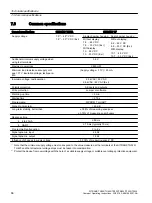
Common specifications
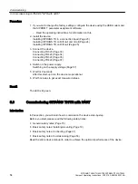
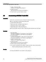
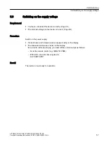
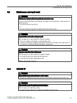
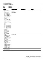
General specifications
SITRANS TH/TR
SITRANS TF
Supply voltage
7.5
1)
... 48
2)
V DC
7.5
1)
... 30
2)
V DC (Ex i)
Single chamber housing Dual chamber housing
Without display:
7.5 ... 48 V DC
7.5 ... 30 V DC (Ex i)
With display:
10 ... 48 V DC
10 ... 30 V DC (Ex i)
Without display:
8.2 ... 48 V DC
8.2 ... 30 V DC (Ex i)
With display:
10.7 ... 48 V DC
10.7 ... 30 V DC (Ex i)
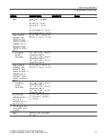
Additional minimum supply voltage when
using test terminals
0.8 V
Maximum power loss
≤ 850 mW
Minimum load resistance at supply volt‐
age > 37 V insulation voltage, test/opera‐
tion
(Supply voltage – 37 V) / 23 mA
Insulation voltage, test/operation
2.5 kVAC / 55 V AC
2.5 kVAC / 42 V AC(Ex i)
Polarity protection
All inputs and outputs
Write protection
Jumper or software
Warming-up time
< 5 min.
Starting time
< 2.75 s
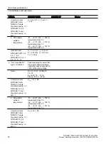
Programming
SIPROM T or HART
Signal-to-noise ratio
> 60 dB
Long-term stability, better than
± 0.05% of measuring span/year
± 0.18% of measuring span/5 years
Response time
● 4 to 20 mA
≤ 55 ms
● HART
≤ 75 ms (typically 70 ms)
Programmable attenuation
0 to 6 s
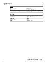
Signal dynamic, input
24 bit
Signal dynamic, output
18 bit
Influence of changes in supply voltage
< 0.005% of measuring span/V DC
1)
Note that the minimum supply voltage must correspond to the value measured at the terminals of the SITRANS TH320/
TH420 and that all external voltage drops must be taken into consideration.
2)
Protect the device from overvoltage with the help of a suitable supply voltage or suitable overvoltage protection equipment.
Technical specifications
7.3 Common specifications
SITRANS TH320/TH420/TR320/TR420/TF320/TF420
66
Compact Operating Instructions, 03/2018, A5E41865021-AA


