Siemens SITRANS F US SONOFLO SONOKIT Manual Download Page 14

SFIDK.PS.029.Y1.02

14

SITRANS F US SONOFLO

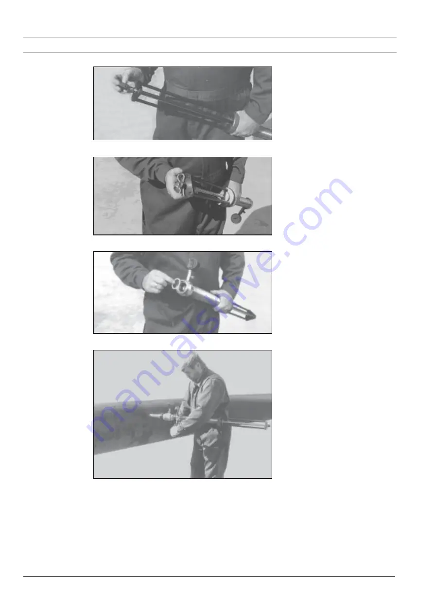
Mount the hex screw nut in the end of the
mandrel.

Mount the spring clip through the nut and
mandrel.

Make sure that the gasket is mounted
and not damaged.

Mount the lock tool on the ball valve. It is
essential that both lock tool and ball
valve have been thoroughly tightened
by means of the hook spanners.

Summary of Contents for SITRANS F US SONOFLO SONOKIT

Page 1: ...Order no FDK 521H1050 SFIDK PS 029 Y1 02 A5E00253229 SITRANS F US SONOFLO Ultrasonic flowmeter Type SONOKIT hot tap mounted 1 and 2 track DN 200 DN 4000 Amendment to product manuals for SONOKIT 1 and 2 tracks 085R9429 s ...

Page 2: ...g of transducer 13 SONOKIT installation with tapping band 18 Introduction 18 Installation 18 Tools for hot tap installation 23 Description of hot tap drilling adaptor 23 Description of hot tap alignment tool for pipe sizes DN 300 DN 1200 24 Description of angle measuring instrument 25 Description of lock tool for inserting or replacement of ultrasonic transducers 26 Ordering 27 ...

Page 3: ...w which will result in inaccurate measuring results Preface This manual describes how to install SONOKIT on filled and pressurized steel pipes hot tap installation The manual is meant as an amendment to the current SONOKIT manuals delivered with the kit and contains only special instructions on the hot tap installation Siemens Flow Instruments recommends that you are familiar with the ordinary ins...

Page 4: ...er holder position Remove the drawing measurement paper Step 2 Place the cradle from the alignment tool on top of the pipe Place the supplied awl through the centre point of the cradle so that the cradle is centered in the middle of the top line X1 X2 Use a spirit lever to check that the cradle is positioned horizontally on to the pipe line Move e g the cradle sideways no matter whether the centre...

Page 5: ...r guiding beam is positioned horizontally and make sure that it is thoroughly fasten ed Use a spirit level to control that the vertical guiding beams are plumb Shorten the transducer holder according to the actual pipe wall thickness t The shortening can be done with a grinder or a saw Cut parallel to the angle of the transducer holder At an angle of 45 the transducer holder is shortened by t x 1 ...

Page 6: ...transducer holders and guid ing beams run parallel to the upper guid ing beam A visual control or a control by means of plumb lines will do Both meth ods require that you stand on the pipe Tack weld the transducer holders in 3 places and check that also after the tack welding they are positioned correctly If so the complete welding can be made Please note that with hot tap installations no mountin...

Page 7: ...m Lmax can now be measured with a meas uring tape on the upper guiding beam Enter the values in the measuring report Valid for standard 160 mm transducers With other transducer lengths set in dimensions correspond ing to these lengths Step 1 The distance between the transducer windows L is calculated based on Lmax as shown The standard transducer length is 160mm If other lengths have been or dered...

Page 8: ...The table shows the required measuring accu racy Measuring the inner diameter Di The inner diameter Di can be calculated on the basis of the circumference C ac cording to the following formula t wall thickness Di C π π π π π 2 x t Measure the angle θ of each trans ducer holder To get the most accurate value it is recommended to take several measurements and calculate the aver age of these Then cal...

Page 9: ...SFIDK PS 029 Y1 02 9 SITRANS F US SONOFLO ...

Page 10: ...SFIDK PS 029 Y1 02 10 SITRANS F US SONOFLO s ...

Page 11: ...o not use grease as it can be difficult to flush out and will pick up drill chips which may damage the transducer o ring Mount a standard hand held drilling machine on the hot tap drill adaptor A drilling machine of 700 1000 W is sufficient Remember to open the valve before drilling Once the drilling is fin ished pull the drill back passed the ball valve Close the ball valve and demount the drill ...

Page 12: ...e silicone plug and carefully put the wires into the transducer To avoid liquids penetrate into the trans ducerduringinstallation mountthebrass adaptor from the lock tool on the trans ducers Be careful when putting the wires into the transducer so that they will not be damaged when screwing on the adap tor Be careful with the mounting of the trans ducer Make sure that the gasket is mounted and not...

Page 13: ...t the transducer on the mandrel of the lock tool Push the snap coupling forward until the 2 teeth of the coupling snaps in place on the transducer Make sure that the lock tool is turned backtorearposition i e maximumlength Place the mandrel with transducer in the lock tool ...

Page 14: ...e end of the mandrel Mount the spring clip through the nut and mandrel Make sure that the gasket is mounted and not damaged Mount the lock tool on the ball valve It is essential that both lock tool and ball valve have been thoroughly tightened by means of the hook spanners ...

Page 15: ...he tripod of the lock tool to stop The tripod must be turned clockwise right to the end If this is not possible the trans ducer may have knocked against an edge on its way through the valve Use a spanner key to turn the screw nut at the end of the mandrel approx 10 roundsclockwise Whenyoufeelastop the transducer has been correctly mounted ...

Page 16: ...e and lock tool from the transducer holder When the transducer has been correctly mounted open the air nozzle to remove the pressure in the lock tool Close the air release valve again If the pressure re establishes the transducer has not been correctly mounted or the gaskets are damaged Remove spring clips and screw nut ...

Page 17: ...ndrel Tighten the transducer by means of the pipe wrench Removethebrassadaptorfromthetrans ducer by means of a fork spanner Mount spring clips and silicone plug The hot tap installation of this transducer is now finished Continue with the re maining transducers following the same procedure ...

Page 18: ...ut please contact Siemens Flow Instruments Each band has an associated Data Sheet with information unique to that band If more than one band of the same size are delivered ensure that each Data Sheet can be identified individually with its band The number of segments in the band depends upon the band circumference and pressure rating Check that the gap numbers stamped on the solid strips at the ed...

Page 19: ...ep 3 Spread the lubricant across the whole surface of the rubber mat on each Tap ping band segment A liberal amount ensures adequate slip between the mat and the pipe surface and will not at all degrade the sealing properties of the band Spread lubricant on the upper side of the feathered edge of each mat to promote good overlap slip Step 4 Place the segments in sequence start ing at the top of th...

Page 20: ...aught The fish plates shall be correctly placed against the tension plates and the folded edge can be hooked beneath them Step 5 Run the nuts to about half way down each stud when a segment is placed to ensure that the later alignment stage can proceed easily The work can be done easily with a hand held drilling machine ...

Page 21: ...ented and that they are either correctly placed over their pre cut holes or that a hot tap drill can fit into the available space The clearance against a nearby wall can be improved by rotating the band up to 45 from the horizontal Step 8 Take note of the recommended torque stamped on the band and set the torque wrench to half that value Torque up all nuts in an even manner making sure that no gap...

Page 22: ...ularly to other gaps to ensure even tightening Step 10 Place the stud covers on the exposed ends to prevent grit collecting in the thread This aids the removal of the band if that should later be required Step 11 The installation of the tapping band is finished Proceed to the hot tap instruc tion for further steps regarding drilling transducer installation and pipe geom etry measurement ...

Page 23: ...th the thread M13 and the other end is connected to a hand held drilling machine 4 SANDVIK holesaw drill Four pcs are supplied with the adaptor SANDVIK holesaws are supplied from SANDVIK AB in Sweden Type of drill Sandflex 3830 25 VIP ø25 5 Flat gasket between drill cylinder and valve Four pcs code No FDK 085B0903 are supplied with the machine 6 O ring for sealing between drill cylinder and drill ...

Page 24: ... mounting on the cradle to keep the alignment barrels in the right position 4 Adaptor to keep the transducer holder in the right position before the welding Two pcs are supplied 5 Holders to keep the vertical rods and the rods holding the transducer in the right position during installation 6 The cradle can be tack welded onto the pipe On non weldable pipes use the enclosed webbing spanners 7 Alig...

Page 25: ...d angle holder 3 Angle holder 4 Alignment rod supplied with the SONOKIT mounting set 5 Transducer holders 6 Slide the blade into the required position and lock with lever 1a 7 To measure the angle open lever 2a and place the angle tool in the angle between pipe and transducer holder Lock lever 2a and read the angle on gauge Siemens Flow Instruments code no FDK 085B5330 1 2 3 3 4 2a 1a 5 ...

Page 26: ...ner key for transducer type SONO 3200 o ring type 2 Hex nut with hole for spring clip 3 Spring clip 4 Hook spanners 5 19 mm spanner key for the lock tool hex nut and brass adaptor 6 Gaskets for ball valve lock tool and brass adaptor 7 Brass adaptor to mount on the transducers 8 Mandrel with snap coupling to hold the transducer 9 Lock tool including ball valve and pressure gauge Siemens Flow Instru...

Page 27: ...NG BAND 1 No of tracks One sound track 1 Two sound tracks 2 2 Circumference of pipe measured 460 mm to 6283 mm 0 9 6 1 961 mm 3 Pipe wall thickness 4 mm to 200 mm 0 8 7 87mm 4 Pressure rating PN 6 A PN 10 max pipe diameter DN 1800 B PN 16 max pipe diameter DN 1200 C ...

Page 28: ...rovement are always welcomed Technical data subject to change without prior notice The reproduction transmission or use of this document or its contents is not permitted without express written authority Offenders will be liable for damages All rights including rights created by patent grant or registration of a utility model or design are reserved Copyright Siemens AG 08 2000 All Rights Reserved ...

Reviews: