


Installation of TFT displays
2 - 3
Siemens AG
SPR2-230.812.02
Page 3 of 8
SIREMOBIL
Medical Solutions
Rev. 02
02.06
CS PS SP
System Manual
Installation of the video and power line cables in the monitor trolley
2
•
TFT display BARCO MVG 1318: Run the video cables (BNC plug - BNC plug) contained
in the scope of supply of the set attachment through the middle cable bush of the moni-
tor trolley, and laterally through the lateral rail to the MEMOSKOP. Plug in and lock the
cables at the OUT1 socket (left display) and OUT2 socket (right display).
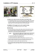
Installation of the support arm on the monitor trolley
2
•
Open the rear cover of the support arm base on the TFT display.
BARCO display
2
•
Run the free cable ends of the new power cables (included in the attachment kit of the
TFT monitor) downwards through the holder of the support arm (2/Fig. 8), through the
center cable bush of the monitor trolley and through the lateral rail to the ON/OFF
assembly (Fig. 7) and connect them to the terminal blocks:
- Connect the brown cable ends to terminal block X2.1.
- Connect the blue cable ends to terminal block X2.2.
- Connect the protective ground (Ge/Gn) to the protective conductor bars (1/Fig. 7).
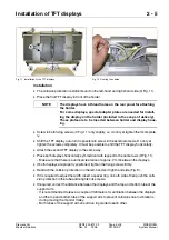
•
Thread the video cables upwards, through the rectangular cable bush (1/Fig. 8) of the
support arm base and further through the holders of the support arm (2/Fig. 8).
•
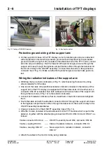
Place the support arm base above the center cable bush (Fig. 8).
•
Starting with the logbook compartment, tighten the screws of the support arm base on
the monitor trolley. Use 4 Allen screws M6 x 20, 4 lock washers and 4 plate washers for
this (Fig. 8).
Fig. 7 ON/OFF assembly
Fig. 8 Installation of the support arm
The new power line cables have a length of approx. 2.6 m and are
equipped with a straight female connector on one cable end.
NOTE


