background image


Functional safety for SIPART PS2 FF 

A5E00489774-02, 10/2013 

35


D


List of Abbreviations/Acronyms 

D.1


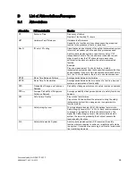
Abbreviations 


Abbreviation 

Full term in English 

Meaning 

FIT 

Failure in Time 

Frequency of failure  
Number of faults within 10

9

 hours 

HFT 

Hardware Fault Tolerance 

Hardware fault tolerance: 
Capability of a function unit to continue executing a required 

function in the presence of faults or deviations. 

MooN 

"M out of N" voting  

Classification and description of the safety-instrumented system 

in terms of redundancy and the selection procedures used. 
A safety-instrumented system or part that consists of "N" 

independent channels. The channels are connected to each 

other in such a way that "M" channels are in each case 

sufficient for the device to perform the safety instrumented 

function. 
Example: 

Pressure measurement: 1oo2 architecture. A safety-

instrumented system decides that a specified pressure limit has 

been exceeded if one out of two pressure sensors reaches this 

limit. In a 1oo1 architecture, there is only one pressure sensor. 

MTBF 

Mean Time Between Failures 

Average period between two failures 

MTTR 

Mean Time To Restoration 

Average period between the occurrence of a fault in a device or 

system and restoration of functionality 

PFD 

Probability of Dangerous Failure on 

Demand 

Probability of dangerous failures of a safety function on demand 

PFD

AVG


Average Probability of Dangerous 

Failure on Demand 

Average probability of dangerous failures of a safety function on 

demand 

SFF 

Safe Failure Fraction 

Proportion of safe failures:  
Proportion of failures without the potential to bring the safety-

instrumented system into a dangerous or non-permissible 

functional status. 

SIL 

Safety Integrity Level 

The international standard IEC 61508 defines four discrete 

Safety Integrity Levels (SIL 1 to SIL 4). Each level corresponds 

to a range of probability for failure of a safety function. The 

higher the Safety Integrity Level of the safety-instrumented 

system, the lower the probability that it will not execute the 

required safety functions. 

SIS 

Safety Instrumented System 

A safety-instrumented system (SIS) executes the safety 

functions that are required to achieve or maintain a safe status 

in a system. It consists of sensors, logic unit/control system and 

final controlling elements. 

Summary of Contents for SIPART PS2 FF

Page 1: ...zusätzlich eine Warnung vor Sachschäden angefügt sein Qualifiziertes Personal Das zu dieser Dokumentation zugehörige Produkt System darf nur von für die jeweilige Aufgabenstellung qualifiziertem Personal gehandhabt werden unter Beachtung der für die jeweilige Aufgabenstellung zugehörigen Dokumentation insbesondere der darin enthaltenen Sicherheits und Warnhinweise Qualifiziertes Personal ist auf G...

Page 2: ...sich dabei um einfach wirkende Stellungsregler zum Anbau an pneumatischen Antrieben mit Federrückstellung Der Stellungsregler entlüftet auf Anforderung oder im Fehlerfall den Ventilantrieb der damit das Ventil in die vorgegebene Sicherheitsstellung bringt Diese Stellungsregler erfüllen folgende Anforderung Funktionale Sicherheit bis SIL 2 nach IEC 61508 bzw IEC 61511 für sicheres Entlüften Siehe a...

Page 3: ...F Seite 6 Sicherheitsbezogenes System im einkanaligen Betrieb SIL 2 Bild 2 1 Sicherheitsbezogenes System im einkanaligen Betrieb Messumformer Automatisierungssystem und Aktor bilden zusammen ein sicherheitsbezogenes System das eine Sicherheitsfunktion ausführt Der Messumformer erzeugt einen prozessbezogenen Messwert der zum Automatisierungssystem übertragen wird Das Automatisierungssystem überwach...

Page 4: ...per auf der Grundelektronik Im Auslieferungszustand ist die Sicherheitsfunktion nicht aktiviert der Jumper steckt auf Position Normal Normal bedeutet ohne Sicherheitsfunktion kein Entlüften des angeschlossenen Antriebs Um die Sicherheitsfunktion zu aktivieren gehen Sie wie folgt vor Stecken Sie den Jumper auf die linke Position in Richtung zu den Klemmen Auf dem Anschlussbild das auf der Baugruppe...

Page 5: ...chaltung Klemmen 81 und 82 wird von einem sicheren System generiert welches mindestens SIL 2 erfüllt Der LOW Pegel beträgt maximal 4 5 V an den Eingangsklemmen Der angeschlossene Antrieb muss einfach wirkend sein und durch Federkraft im folgenden Fall das Ventil in die sichere Endlage bringen Bei einem Kammerdruck Y1 Anschluss bis zu ein Drittel des maximal verfügbaren Zuluftdrucks Pz Anschluss De...

Page 6: ...Einheit 100 Hübe d h der Weg zwischen 0 und 100 und zurück Der Wert wird alle 15 Minuten in einen nicht flüchtigen Speicher geschrieben Er lässt sich mit der Inkrement Taste auf null setzen 2 CHDIR Anzahl Richtungsänderungen Kommunikationsobjekt NUMBER_DIRECTION_CHANGE Im Regler wird jede aus der Totzone herausgehende Richtungsänderung notiert und zur Anzahl der Richtungsänderungen aufaddiert Der ...

Page 7: ...de werden im Display angezeigt OFF Die Partial Stroke Test Funktion ist im Konfigurationsmenü deaktiviert FdIni Failed PST Initialization Die Partial Stroke Test Referenzsprungzeitmessung ist fehlgeschlagen notSt No Test Es wurde noch kein Partial Stroke Test durchgeführt gemessene Sprungzeit in Sekunden Der letzte Partial Stroke Test wurde erfolgreich durchgeführt SdtSt Stopped Test Der letzte Pa...

Page 8: ...tionsmenü deaktiviert ist wird OFF angezeigt 17 ZERO Nullpunktverschiebung Kommunikationsobjekt ZERO_VALUE Anzeige der aktuellen Verschiebung des unteren Hartanschlags gegenüber seinem Initialisierungswert Voraussetzung der Ermittlung ist die Aktivierung der Dichtschließfunktion unten Parameter YCLS im Konfigurationsmenü Falls die zu Grunde liegende Funktion im Konfigurationsmenü deaktiviert ist w...

Page 9: ...te entsprechen entweder dem manuell eingestellten Wert des Parameters DEBA oder dem automatisch vom Gerät adaptierten Wert wenn DEBA auf Auto eingestellt wurde 26 SSUP Langsamgangzone auf Kommunikationsobjekt SERVO_GAIN_UP Dieser Parameter ist für Spezialanwendungen einstellbar 27 SSDN Langsamgangzone zu Kommunikationsobjekt SERVO_GAIN_DOWN Die Langsamgangzone ist der Bereich des Reglers in dem pu...

Page 10: ...den Antrieb Im Ventilblock befinden sich zwei Vorsteuerventile Die charakteristische Lebensdauer des Ventilblocks ist belastungsabhängig Sie beträgt durchschnittlich ca 200 Millionen Schaltspiele für jedes der beiden Vorsteuerventile bei symmetrischer Beanspruchung Die Anzahl der Ansteuervorgänge der Schaltspiele dient der Beurteilung der Schalthäufigkeit des Ventilblocks Zählvorgang bei einfach w...

Page 11: ...0 50 70 90 95 5 10 30 50 70 90 95 Einteilung der Stellbereiche Die 8 Betriebsstundenzähler können Sie durch Drücken der Inkrement Taste für mindestens 5 Sekunden gemeinsam auf null setzen TIPP Da die Stellbereiche am Ende des Diagnosemenüs angeordnet sind drücken Sie zusätzlich zur Betriebsartentaste die Dekrement Taste mehrmals So erreichen Sie schnell die Diagnosenummern Hinweis Alle Diagnosewer...

Page 12: ...el Y2 1 Display Verstellrad Rutschkupplung Ausgang Stelldruck Y2 1 Anschlussklemmen Optionsmodule Tasten Anschlussklemmen Grundgerät Getriebeübersetzungsumschalter 2 Deckelsicherung 1 bei doppelt wirkenden Antrieben 2 nur bei geöffneten Stellungsregler möglich Bild A 2 Ansicht des Stellungsreglers im druckfesten Gehäuse ...

Page 13: ...1 stehen Initialisierung aus Endlage gestartet und Reaktionszeit von max 1 min nicht abgewartet Netzdruck nicht angeschlossen oder zu gering Bis zu 1 min Wartezeit erforderlich Initialisierung nicht aus Endlage starten Netzdruck sicherstellen Stellungsregler bleibt im RUN 2 stehen Getriebeübersetzungsumschalter und Parameter 2 YAGL sowie realer Hub stimmen nicht überein Hub auf Hebel falsch einges...

Page 14: ... nicht oder nur in einer Richtung bewegen Feuchtigkeit im Ventilblock Piezoventil schaltet nicht Es ist auch kein leises Klicken hörbar wenn im Handbetrieb auf Taste oder gedrückt wird Schraube zwischen Abdeckhaube und Ventilblock nicht fest angezogen oder Haube verklemmt Schraube festziehen evtl Verklemmung beseitigen Schmutz Späne Partikel im Ventilblock Reparatur oder Neugerät integrierte Feins...

Page 15: ...siehe oben Siehe oben Fehlertabelle 3 A 3 5 Abhilfemaßnahmen Tabelle 4 Fehlerbild Symptomatik Mögliche Ursache n Abhilfemaßnahmen Im stationären Automatikbetrieb konstanter Sollwert und im Handbetrieb schalten beide Piezoventile ständig abwechselnd Antrieb pendelt um einen Mittelwert Haftreibung der Stopfbuchse von Armatur bzw Antrieb zu groß Haftreibung reduzieren oder Totzone von Stellungsregler...

Page 16: ...ällt total aus auch keine Darstellung im Display Elektrische Hilfsenergie nicht ausreichend Elektrische Hilfsenergie überprüfen Bei sehr hoher Dauerbeanspruchung durch Vibrationen Schwingungen Können sich Schrauben der elektrischen Anschlussklemmen lösen Können elektrische Anschlussklemmen und oder elektronische Bauelemente losgerüttelt werden Schrauben festziehen und mit Siegellack sichern Repara...

Page 17: ...len MTTR Mean Time To Restoration Mittlere Zeitdauer zwischen dem Auftreten eines Fehlers in einem Gerät oder System und der Wiederherstellung PFD Probability of Dangerous Failure on Demand Wahrscheinlichkeit Gefahr bringender Ausfälle einer Sicherheitsfunktion im Anforderungsfall PFDAVG Average Probability of Dangerous Failure on Demand Mittlere Wahrscheinlichkeit Gefahr bringender Ausfälle einer...

Page 18: ...em Wahrscheinlichkeitsbereich für das Versagen einer Sicherheitsfunktion Je höher der SIL des sicherheitsbezogenen Systems ist desto höher ist die Wahrscheinlichkeit dass die geforderte Sicherheitsfunktion funktioniert Der erreichbare SIL wird durch folgende sicherheitstechnischen Kenndaten bestimmt Mittlere Wahrscheinlichkeit Gefahr bringender Ausfälle einer Sicherheitsfunktion im Anforderungsfal...

Page 19: ...e a warning relating to property damage Qualified Personnel The product system described in this documentation may be operated only by personnel qualified for the specific task in accordance with the relevant documentation in particular its warning notices and safety instructions Qualified personnel are those who based on their training and experience are capable of identifying risks and avoiding ...

Page 20: ...sitioners for mounting on pneumatic actuators with spring return The positioner automatically depressurizes the valve actuator on demand or in case of faults which thus switches the valve to the specified safety position This positioner meets the following requirement Functional safety up to SIL 2 in accordance with IEC 61508 or IEC 61511 for safe venting See also Functional safety in process inst...

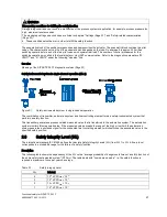
Page 21: ...ted system in single channel operation SIL 2 Figure 2 1 Safety instrumented system in single channel operation The combination of transmitter automation system and final controlling element forms a safety instrumented system that performs a safety function The transmitter generates a process related measured value that is transferred to the automation system The automation system monitors this mea...

Page 22: ...c electronics The safety function is not activated in the delivered state the Jumper is in the Normal position Normal means Without safety function no depressurizing of the connected actuator To activate the safety function proceed as follows Insert the Jumper in the left position facing the terminals This corresponds to the position Shut Down enabled on the wiring diagram present on the module co...

Page 23: ...ions leading to an increased dynamic pressure In particular a silencer is only allowed if icing or other contamination is ruled out The restrictor in the Y1 circuit may not be completely closed during operation The auxiliary pneumatic power is free of oil water and dirt in line with DIN ISO 8573 1 maximum class 2 The average temperature viewed over a long period is 40 C Fault rates are calculated ...

Page 24: ...larms 1 Communication object NUMBER_ALARMS_1 5 A2CNT number of alarms 2 Communication object NUMBER_ALARMS_2 The response of alarms 1 and 2 is counted using these two counters Activation of alarms using the AFCT parameter is a requirement for this see below The counters can be set to zero using the increment button 6 HOURS operating hours Communication object RB HOURS The runtime meter is incremen...

Page 25: ...stroke test A manual partial stroke test is not started Strt start A manual partial stroke test is started five seconds after pressing the button StoP stop The current partial stroke test is interrupted 12 PRPST time since last partial stroke test Communication object PST PST_PREV_TIME The time in days elapsed since the last partial stroke test is displayed here In addition the following status me...

Page 26: ... determination is activation of the Tight closing function OPEN YCLS parameter in the configuration menu If the underlying function is deactivated in the configuration menu OFF is displayed 19 PAVG position average Communication object POS_AVG_VALUE The last calculated comparison average is displayed here The following status messages are also available OFF The underlying function is deactivated i...

Page 27: ...set for special applications 27 SSDN short step zone DOWN Communication object SERVO_GAIN_DOWN The short step zone is the zone of the closed loop controller in which control signals are issued in a pulsed manner The impulse length is thus proportional to the control deviation If the control deviation is outside the short step zone the valves are controlled using permanent contact This parameter ca...

Page 28: ...these two parameters The pneumatic block of the positioner pressurizes and depressurizes the actuator The pneumatic block contains two pilot valves The characteristic service life of the pneumatic block depends on the load On average it is approx 200 million switching operations for each of the two pilot valves with symmetrical load The number of control procedures for the switching operations ser...

Page 29: ...sponding section actuating range every hour This helps in drawing conclusions about the past operating conditions and especially in assessing the control properties of the control loop and the entire control valve The actuating range is divided as follows Actuating range WT00 WT05 WT10 WT30 WT50 WT70 WT90 WT95 Actuating range section 5 10 30 50 70 90 95 5 10 30 50 70 90 95 Division of actuating ra...

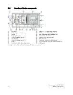
Page 30: ... Exhaust air outlet with a sound absorber Purging air selector Transmission ratio selector Output Actuating pressure Y1 Friction clutch adjustment wheel Input Supply air Basic electronics Output Actuating pressure Y2 Connecting terminals of option modules Buttons Shield connection only with a Makrolon enclosure Restrictor Y2 for double acting actuators Cable gland Figure A 1 View of the positioner...

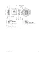
Page 31: ...tor Y2 1 Display Friction clutch adjustment wheel Output Actuating pressure Y2 1 Connecting terminals of option modules Buttons Connecting terminals of basic device Transmission ratio selector 2 Safety catch 1 for double acting actuators 2 only possible when positioner is open Figure A 2 View of positioner in flameproof enclosure ...

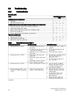
Page 32: ...response time of a maximum of 1 minute was not observed Network pressure not connected or it is too low A waiting time of up to 1 minute is essential Do not start initialization from the end position Provide the network pressure Positioner remains in RUN 2 Transmission ratio selector and parameter 2 YAGL and the real stroke do not match Incorrectly set stroke on the lever Piezo valve does not acti...

Page 33: ...sits on the contacts between the electronic printed circuit board and the pneumatic block may develop due to abrasion owing to continuous loads resulting from strong vibrations Clean all contact surfaces with spirit if required bend the pneumatic block contact springs Fault table 2 C 3 4 Remedial measures table 3 Fault profile symptoms Possible cause Remedial measures Actuator does not move Compre...

Page 34: ...mA Supply pressure too low Load on the feeding controller or system output is too low Increase supply pressure insert ballast converter Select 3 4 wire mode Error table 4 C 3 6 Remedial measures table 5 Fault profile symptoms Possible cause s Remedial measures Zero point displaces sporadically 3 Impact or shock loads result in accelerations so high that the friction clutch moves e g due to vapor s...

Page 35: ...n Time Between Failures Average period between two failures MTTR Mean Time To Restoration Average period between the occurrence of a fault in a device or system and restoration of functionality PFD Probability of Dangerous Failure on Demand Probability of dangerous failures of a safety function on demand PFDAVG Average Probability of Dangerous Failure on Demand Average probability of dangerous fai...

Page 36: ... SIL 4 Every level indicates a probability range for the failure of the safety function The higher the SIL of the safety instrumented system the higher the probability that the required safety function works The achievable SIL is determined by the following safety instrumented characteristics Average probability of dangerous failures of a safety function on demand PFDAVG Hardware fault tolerance H...

Reviews:

Related manuals for SIPART PS2 FF