Functional safety for SIPART PS2 FF
28
A5E00489774-02, 10/2013
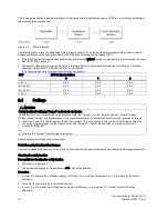
31 T1 to 39 T9 - number of operating hours in temperature ranges T1 to T9
Communication object: [RB.TEMPERATURE_HOURS]
Statistics about the duration of operation in different temperature ranges is maintained in the device. An average of the
measured temperature is taken every hour and the counter assigned to the corresponding temperature range is
incremented. This helps in drawing conclusions about the past operating conditions of the device and the entire control
valve.
The temperature ranges are classified as follows:
T1
T2
T3
T4
T5
T6
T7
T8
T9
Temperature range [°C]
-
≥
-30
≥
-15
≥
0
≥
15
≥
30
≥
45
≥
60
≥
75
≥
-30
< -15
< 0
< 15
< 30
< 45
< 60
< 75
-
Temperature range [°F]
-
≥
-22
≥
5
≥
32
≥
59
≥
86
≥
113
≥
140
≥
167
< -22
< -5
< 32
< 59
< 86
< 113 < 140 < 167 -
Operating hours in temperature ranges T1 to T9
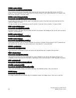
40 VENT1 - counter for pilot valve 1
Communication object: [NUMBER_CYCLES_VALVE_1]
41 VENT2 - counter for pilot valve 2
Communication object: [NUMBER_CYCLES_VALVE_2]
Control procedures of the pilot valves in the pneumatic block of the positioner are counted and displayed in these two
parameters.
The pneumatic block of the positioner pressurizes and depressurizes the actuator. The pneumatic block contains two pilot
valves. The characteristic service life of the pneumatic block depends on the load. On average it is approx. 200 million
switching operations for each of the two pilot valves with symmetrical load. The number of control procedures for the
switching operations serves to assess the switching frequency of the pneumatic block.
Counting procedure for single-acting actuators:
●
Pressurize => 40 VENT1
●
Depressurize => 41 VENT2
Counting procedure for double-acting actuators:
●
Pressurize (Y2) / Depressurize (Y1) => 40 VENT1
●
Depressurize (Y1) / Pressurize (Y2) => 41 VENT2
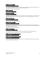
42 STORE - save maintenance data
Communication object: [no correspondence]
A save function can be initiated by pressing the increment button for at least 5 seconds. The diagnostics data 7 to 18 is
saved in the non-volatile memory as "data of last maintenance". This diagnostics data contains selected values whose
changes can give information about mechanical wear and tear of the valve.
This function is usually used over the bus communication with this transducer block method:
"Maintenance Info Save/Reset" --> "safe maintenance info".
The data is saved in the communication object "PREV_CALIB_VALUES".


