A2: Various NC/PLC interface signals and functions
1.3 Functions
Basic Functions
58
Function Manual, 09/2011, 6FC5397-0BP40-2BA0
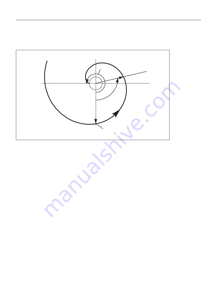
Limit angle
If AR is used to program an involute leading to the base circle with an angle of rotation that is greater than the
maximum possible value, an alarm is output and program execution aborted.
Figure 1-8
Limited angle of rotation towards base circle
The alarm display can be suppressed using the following parameter settings:
MD21016 $MC_INVOLUTE_AUTO_ANGLE_LIMIT = TRUE (automatic angle limitation for involute interpolation)
The programmed angle of rotation is then also limited automatically and the interpolated path ends at the point at
which the involute meets the base circle. This, for example, makes it easier to program an involute, which starts
at a point outside the base circle and ends directly on it.
Tool radius compensation
2 1/2 D tool-radius compensation is the only tool-radius compensation function permitted for involutes. If 3D tool-
radius compensation is active (both circumferential and face milling), when an involute is programmed,
machining is interrupted with alarm 10782.
With 2 1/2 D tool-radius compensation, the plane of the involute must lie in the compensation plane. or else alarm
10781 will be generated. It is however permissible to program an additional helical component for an involute in
the compensation plane.
Dynamic response
Involutes that begin or end on the base circle have an infinite curvature at this point. To ensure that the velocity is
adequately limited at this point when tool-radius compensation is active, without reducing it too far at other points,
the "Velocity limitation profile" function must be activated:
MD28530 $MC_MM_PATH_VELO_SEGMENTS > 1 (number of memory elements for limiting the path velocity)
A setting of 5 is recommended. This setting need not be made if only involute sections are used, which have radii
of curvature that change over a relatively small area.
6WDUWSRLQW
$5
$5PD[


