


PP
PP
PP
[
2XWSXW
FDP
2XWSXW
FDP
2XWSXW
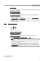
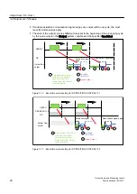
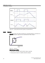
Figure 3-18 OR operation of two output cams
Note
If hardware output cams are configured, you can configure an I/O variable in the symbol
browser for monitoring.
See also
Output cam configuration (Page 38)
3.2.2.5
Simulation
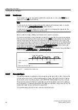
Operation can be simulated by means of the simulation commands on the output cam. The
output cam status is then not output to the hardware output. In simulation mode, a hardware
cam behaves as a software cam. It is then only used for programming purposes.
If an active output cam is switched to simulation mode (_enableOutputCamSimulation), the
output cam status remains the same, and only the control of the output is reset or interrupted.
3.2.2.6
Inversion
The inversion of single output cams is available and is set on the _enableOutputCam command
by a parameter (invertOutput).
3.2.3
Configure Units
You can define the basic units for each technology object. The same physical variables can
have different units in different technology objects. These are converted:
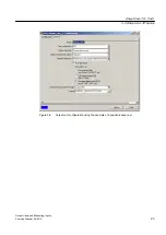
How to configure the units:
1. In the project navigator, open the context menu for the technology object.
2. In the context menu, select Expert > Configure units. The Configure Units window appears
in the working area.
3. Select the unit for the physical variables. These units are used for the technology object,
e.g. s for time units.
Output Cam TO - Part I
3.2 Output cam TO basics
Output Cams and Measuring Inputs
Function Manual, 04/2014
35


