


Mechanical mounting
4.7 Mounting of rotating unions on 1PH8 hollow-shaft motors
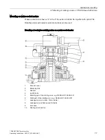
1PH808/1PH810 main motors
68
Operating Instructions, 04/2017, 610.48004.40f
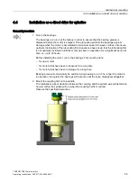
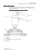
With opening seals, the sealing surfaces are separated when there is no coolant pressure,
e.g. during a tool change. In this case, coolant runs out of the supply line and out of the
motor shaft through the opened seal. This leakage and also the leakage due to wear of the
sealing rings must be guided away via the leakage lines.
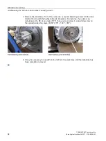
NOTICE
Motor failure due to incorrectly mounted leakage line
If the leakage line does not lead downward, the leakage can flood the rotating union and
the motor. This can result in failure of the rotating union and motor.
To ensure the leakage is led away, the leakage line must always lead downward so that
nothing can flow back.
•
When mounting, ensure that the leakage line always leads downward.
NOTICE
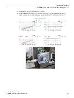
Axial forces due to coolant pressure
Coolant under high pressure (usually 40 to 90 bar) flows via the mounted rotating union
through the sequence of holes in the drive train:
•
Rotating union
•
Motor
•
Spindle
•
Tool.
Due to the different hole diameters and the gap, different cross sections (areas) occur
along the coolant flow, which can produce axial forces due to the coolant pressure. These
can be 4 to 12.7 N/mm
2
, depending on the coolant pressure.
Summary of Contents for SIMOTICS M-1PH8
Page 1: ......
Page 2: ......
Page 8: ...Introduction 1PH808 1PH810 main motors 8 Operating Instructions 04 2017 610 48004 40f ...
Page 12: ...Table of contents 1PH808 1PH810 main motors 12 Operating Instructions 04 2017 610 48004 40f ...
Page 148: ...Spare parts 1PH808 1PH810 main motors 148 Operating Instructions 04 2017 610 48004 40f ...
Page 185: ......
Page 186: ......


