background image


SIMATIC RF642A 
J31069-D0226-U001-A

222

1-7618, 11/2010 

17


Approvals & certificates 

Table 4  6GT2812-1GA08 

Certificate 

Description 


Conformity in accordance with R&TTE directive 

in association with the readers and accessories used 

Table 5  6GT2812-1GA08 

Standard 


Federal Communications 

Commission  

FCC CFR 47, Part 15 sections 15.247 
Radio Frequency Interference Statement  

This equipment has been tested and found to comply with the limits for a Class B 

digital device, pursuant to Part 15 of the FCC Rules.  
The FCC approval is granted in association with the FCC approval of the following 

RF600 readers: 
●  FCC ID: NXW-RF630R 
●  FCC ID: NXW-RF670 

Industry Canada Radio Standards 

Specifications 

RSS-210 Issue 7, June 2007, Sections 2.2, A8 
The approval for Industry Canada is granted in association with the Industry 

Canada approval of the following RF600 readers: 
●  IC: 267X-RF630 
●  IC: 267X-RF670 


This product is UL-certified for the USA and Canada. 
It meets the following safety standard(s):  
UL 60950-1 - Information Technology Equipment Safety - Part 1: General 

Requirements 
CSA C22.2 No. 60950 -1 - Safety of Information Technology Equipment 
UL Report E 205089 


Siemens AG 

Industry Sector 

Postfach 48 48 

90026 NÜRNBERG 


SIMATIC RF642A 

J31069-D0226-U001-A

2

-7618, 1

2

/2010 

Summary of Contents for SIMATIC RF642A

Page 1: ...Anschluss an den Reader wird noch ein Antennenkabel benötigt z B 6GT2815 0BH30 anschließbare Reader Alle RF600 Reader mit externen Antennenanschlüssen Maße in mm 185 x 185 x 45 Schutzart IP65 1 siehe RF600 Systemhandbuch Frequenzbereiche Die Antenne ist breitbandig verfügbar Sie kann daher für zwei verschieden Frequenzbereiche eingesetzt werden die jeweils für die Regionen Europa und China USA bes...

Page 2: ...Befestigungsarten VESA 100 Befestigungssystem Zur Befestigung der Antenne ist ein genormtes VESA 100 Befestigungssystem vorgesehen Das Befestigungssystem besteht aus vier Befestigungsbohrungen für M4 Schrauben im Abstand von 100 mm Damit ist die Montage geeignet für Montage auf metallischen und nicht metallischen Untergründen Hinweis Für optimale Wellenausbreitung sollte die Antenne nicht von leit...

Page 3: ...erwendung von Siemens Antennenkabel Um eine optimale Funktion der Antenne zu gewährleisten wird die Verwendung eines Siemens Antennenkabels gemäß Zubehörliste empfohlen Zugentlastung Für das Antennenkabel ist eine Zugentlastung vorzusehen wie in folgender Grafik gezeigt RF642A Antennenanschluss 30 cm Anschlusskabel RF600 Antennenkabel Zugentlastung sollte an dieser Stelle erfolgen Bild 1 Zugentlas...

Page 4: ...ar polarisiert ist muss die Ausrichtung der verwendeten Transponder in Bezug auf die Antenne beachtet werden Grundsätzlich müssen die Polarisationsachsen von Antenne und Transponder parallel zueinander verlaufen Das Symbol auf der Antenne stellt den Verlauf der Polarisationsachse grafisch dar 3RODULVDWLRQVDFKVH Bild 2 Polarisationsachse ...

Page 5: ...J31069 D0226 U001 A2 0018 12 2010 5 Ausrichtung Die folgende Grafik zeigt die optimale Ausrichtung der RF600 Transponder zur Antenne RF642A 6 0 7 5 5 7 5 7 5 7 5 7 5 7 HQ 5 5 5 7 Bild 3 Antennen Transponderausrichtung ...

Page 6: ...nde Diagramm zeigt die Abhängigkeit folgender Faktoren Ausrichtungswinkels des Transponders zur Antenne Maximale Reichweite der Antenne 6 0 7 5 LQNHODEZHLFKXQJ GHU 3RODULVDWLRQVDFKHQ YRQ QWHQQH XQG 7DJ UDG PD 5HLFKZHLWH r r r r r r r r r r r r r r r r r r Bild 4 Winkeldiagramm Ausrichtung ...

Page 7: ...P 800 mW EIRP 29 15 dBm EIRP nicht überschritten wird muss die einzustellende Sendeleistung ggf um 3 dB reduziert werden Im Folgenden finden Sie die Leistungseinstellungen über den Parameter distance_limiting für ausschließlich lesende Datenzugriffe es darf kein WRITE INIT Befehl über die SIMATIC an einen Transponder erfolgen und den Fall dass schreibende oder lesende Datenzugriffe es gibt mindest...

Page 8: ...trahlungsleistung nach EN 302 208 V1 2 1 RF600 Systeme die innerhalb der EU EFTA oder Türkei ETSI in Betrieb genommen werden dürfen mit einer RF642A Antenne bis zu einer maximalen Strahlungsleistung von 500 mW ERP bzw 27 dBm ERP 800 mW EIRP 29 15 dBm EIRP betrieben werden Durch Einstellung der Strahlungsleistung von 500 mW ERP bzw 27 dBm ERP 800 mW EIRP 29 15 dBm EIRP des RF642A Antennengewinns vo...

Page 9: ... überschritten Betrieb innerhalb Chinas Durch Einstellung einer max Strahlungsleistung von 2000 mW ERP bzw 33 dBm ERP 3250 mW EIRP 35 dBm EIRP des RF642A Antennengewinns von 7 dBi sowie der zum Antennenkabel gehörigen Kabeldämpfung siehe Tabelle Seite 3 wird die entsprechende Sendeleistung vom Reader korrekt konfiguriert Betrieb innerhalb der USA Kanada ACHTUNG Beschränkung der Sendeleistung auf 4...

Page 10: ... Antenne wie in der nachstehenden Abbildung betrachtet wird r r r r r r Bild 5 Bezugssystem Der Abstrahl Empfangswinkel der Antenne ist durch den Winkel zwischen den zwei 3 dB Punkten definiert Welcher Reichweite in die dB Werte der Diagramme entsprechen können Sie dieser Tabelle entnehmen Beachten Sie dass die im Folgenden grafisch dargestellten Messungen in einer reflexionsarmen Umgebung durchge...

Page 11: ... 0018 12 2010 11 Richtcharakteristik im ETSI Frequenzband HZLQQ G L LQNHO UDG Charakteristik der vertikalen Raumebene der Antenne Charakteristik der horizontalen Raumebene der Antenne Bild 6 Richtcharakteristik RF642A im ETSI Fequenzband ...

Page 12: ...trahl Empfangswinkel der Antenne ist durch den Winkel zwischen den zwei 3 dB Punkten entspricht der halben Leistung bezogen auf Maximalleistung definiert Welcher Reichweite in die dB Werte der Diagramme entsprechen können Sie dieser Tabelle entnehmen Beachten Sie dass die im Folgenden grafisch dargestellten Messungen in einer reflexionsarmen Umgebung durchgeführt wurden In normal reflektierender U...

Page 13: ...2 2010 13 Richtcharakteristik der RF642A im FCC Frequenzband HZLQQ G L LQNHO UDG Charakteristik der vertikalen Raumebene der Antenne Charakteristik der horizontalen Raumebene der Antenne Bild 8 Richtcharakteristik der RF642A im FCC Frequenzband ...

Page 14: ... dBi Wert und einem zweiten dBi Wert Abweichung vom maximalen Antennengewinn dBr Reichweite der Antenne 0 100 3 70 6 50 9 35 12 25 15 18 18 13 Beispiel Wie man der Richtcharakteristik im ETSI Frequenzband Seite 11 entnehmen kann ist der maximale Antennengewinn in der horizontale Raumebene 6 dBi In dieser Raumebene und mit paralleler Polarisationsachse ist bei 70 bzw 300 der Antennengewinn auf ca 0...

Page 15: ...2000 mW Impedanz 50 Ohm ETSI Frequenzband 6 dBi Antennengewinn FCC Frequenzband 7 dBi VSWR Stehwellenverhältnis max 1 4 Polarisation linear polarisiert ETSI Frequenzband Horizontale Ebene 75 Vertikale Ebene 70 Siehe Antennediagramm ETSI Seite 11 Öffnungswinkel für Senden Empfangen FCCequenzband Horizontale Ebene 80 Vertikale Ebene 70 Siehe Antennediagramm FCC Seite 13 ETSI Frequenzband 10 dB Vor R...

Page 16: ...SIMATIC RF642A 16 J31069 D0226 U001 A2 0018 12 2010 Maßbild s s Bild 9 Maßbild RF642A Alle Maßangaben in mm ...

Page 17: ...usammenhang mit der FCC Zulassung der folgenden RF600 Readern erteilt FCC ID NXW RF630R FCC ID NXW RF670 Industry Canada Radio Standards Specifications RSS 210 Issue 7 June 2007 Sections 2 2 A8 Die Zulassung für Industry Canada wird in Zusammenhang mit der Zulassung Industry Canada der folgenden RF600 Readern erteilt IC 267X RF630 IC 267X RF670 Dieses Produkt ist nach UL für USA und Canada zertifi...

Page 18: ...equired for connection to the reader e g 6GT2815 0BH30 Readers that can be connected All RF600 readers with external antenna connections Dimensions in mm 185 x 185 x 45 Degree of protection IP65 1 See RF600 system manual Frequency bands The antenna is available for broadband It can therefore be used for two different frequency bands that have been specified for the regions of Europe and China USA ...

Page 19: ...Installation and assembly RF642A mounting types VESA 100 mounting system A standardized VESA 100 mounting system is provided to mount the antenna The mounting system consists of four fixing holes for M4 screws at intervals of 100 mm This is therefore suitable for Mounting on metallic and non metallic backgrounds Note To achieve optimum wave propagation the antenna should not be surrounded by condu...

Page 20: ...le To ensure optimum functioning of the antenna it is recommended that a Siemens antenna cable be used in accordance with the list of accessories Strain relief The antenna cable is provided with strain relief as shown in the following diagram RF642A antenna connection 30 cm connecting cable RF600 antenna cable Strain relief should take place at this position Figure 1 Strain relief Bending radii of...

Page 21: ...42A antenna has linear polarization it is necessary to consider the alignment of the transponders with regard to the polarization axis of the antenna The polarization axes of antenna and transponder must always be parallel The symbol on the antenna indicates the polarization axis 3RODUL DWLRQ D LV Figure 2 Polarization axis ...

Page 22: ...1069 D0226 U001 A2 7618 12 2010 5 Alignment The following diagram shows the optimum alignment of the RF600 transponders to the RF642A antenna 6 0 7 5 5 7 5 7 5 7 5 7 5 7 HQ 5 5 5 7 Figure 3 Antenna transponder alignment ...

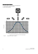
Page 23: ...ollowing diagram shows the dependence of the following factors Alignment angle of transponder to antenna Maximum range of antenna 6 0 7 5 QJOH GHYLDWLRQ RI WKH SRODUL DWLRQ D HV RI DQWHQQD DQG WDJ GHJUHHV 0D UDQJH r r r r r r r r r r r r r r r r r r Figure 4 Angle deviation diagram for alignment ...

Page 24: ...be issued to a transponder via the SIMATIC and for the case that write or read data accesses should take place within one sequence at least one WRITE INIT command is issued to a transponder via the SIMATIC ANT1 ANT2 hex Cable designation Order No Length m Cable loss dB Read Read or write 1 Antenna cable 6GT2815 0BH30 3 1 0 6 0 3 Antenna cable 6GT2815 1BN10 10 2 0 7 0 4 Antenna cable 6GT2815 0BN10 ...

Page 25: ...diated power of 500 mW ERP or 27 dBm ERP 800 mW EIRP 29 15 dBm EIRP the RF642A antenna gain of 6 dBi and the cable loss associated with the antenna cable see table Page 3 the radiated power of the reader is correctly configured and the radiated power at the antenna is thus not exceeded Operation in China By setting a max radiated power of 2000 mW ERP or 33 dBm ERP 3250 mW EIRP 35 dBm EIRP the RF64...

Page 26: ...iated power at the antenna is thus not exceeded Operation in China By setting a max radiated power of 2000 mW ERP or 33 dBm ERP 3250 mW EIRP 35 dBm EIRP the RF642A antenna gain of 7 dBi and the cable loss associated with the antenna cable see table Page 3 the radiated power is correctly configured in the reader Operation in the USA Canada NOTICE Limitation of the radiated power to 4000 mW EIRP 36 ...

Page 27: ... alignment is given when the antenna elevation is provided as shown in the following figure r r r r r r Figure 5 Reference system The half power beam width of the antenna is defined by the angle between the two 3 dB points Which range in corresponds to the dB values in the patterns can be obtained from this table Note that the measurements presented graphically below were carried out in a low refl...

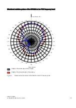
Page 28: ...Directional radiation pattern in the ETSI frequency band PSOLILFDWLRQ G L QJOH GHJUHHV Pattern of the vertical plane of the antenna Pattern of the horizontal plane of the antenna Figure 6 Directional radiation pattern of RF642A in the ETSI frequency band ...

Page 29: ...r r r Figure 7 Reference system The half power beam width of the antenna is defined by the angle between the two 3 dB points corresponding to half the power referred to the maximum power Which range in corresponds to the dB values in the patterns can be obtained from this table Note that the measurements presented graphically below were carried out in a low reflection environment Deviations can th...

Page 30: ...nal radiation pattern of the RF642A in the FCC frequency band PSOLILFDWLRQ G L QJOH GHJUHHV Pattern of the vertical plane of the antenna Pattern of the horizontal plane of the antenna Figure 8 Directional radiation pattern of the RF642A in the FCC frequency band ...

Page 31: ...difference between the maximum dBi value and a second dBi value Deviation from maximum antenna gain dBr Read write range 0 100 3 70 6 50 9 35 12 25 15 18 18 13 Example As can be seen in Directional radiation pattern in the ETSI frequency band Page 11 the maximum antenna gain in the horizontal plane is 6 dBi In this plane and with the parallel polarization axis at 70 or 300 the antenna gain dropped...

Page 32: ...0 Ohm ETSI frequency band 6 dBi Antenna gain FCC frequency band 7 dBi VSWR standing wave ratio max 1 4 Polarization Linear polarization ETSI frequency band Horizontal plane 75 Vertical plane 70 See ETSI antenna pattern Page 11 Half power beam width for transmission and reception FCC frequency band Horizontal plane 80 Vertical plane 70 See FCC antenna pattern Page 13 ETSI frequency band 10 dB Front...

Page 33: ...SIMATIC RF642A 16 J31069 D0226 U001 A2 7618 12 2010 Dimension drawing s s Figure 9 Dimensional drawing of RF642A All dimensions in mm ...

Page 34: ...s granted in association with the FCC approval of the following RF600 readers FCC ID NXW RF630R FCC ID NXW RF670 Industry Canada Radio Standards Specifications RSS 210 Issue 7 June 2007 Sections 2 2 A8 The approval for Industry Canada is granted in association with the Industry Canada approval of the following RF600 readers IC 267X RF630 IC 267X RF670 This product is UL certified for the USA and C...

Reviews: