Description of the device
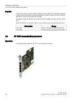
1.1 CP 1604 communications processor
CP 1604 / CP 1616
Operating Instructions, 02/2017, C70000-G8976-C218-08
13
LEDs on the "RJ-45 connection board for CP 1604"
Within the frame of each RJ-45 jack, there are 2 LEDs.
The green LED is lit when a connection is established (Link LED).
The yellow LED is lit when sending and receiving (Activity LED).
Virtual LEDs
Note that apart from the visible LEDs there are also two "virtual" LEDs in the firmware.
These are the operating mode LEDs RUN and STOP. They do not exist physically but can
nevertheless be queried using SNMP. They are on in the RUN or STOP mode and never
flash normally or quickly.
1.1.1
40-pin male connector for connection of the RJ-45 connection board for CP
1604
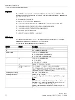
Description
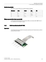
The 40-pin connector is used to connect the ribbon cable from the RJ-45 connection board
for CP 1604. This has the Ethernet connectors that allow network operation.
The signals are processed in the integrated 4-port real-time switch of the CP 1604.
Ethernet connectors
The CP 1604 communications processor is intended for operation in Ethernet networks.
It also has the following features:
●
The connectors are designed for 10BaseT and 100BaseTX (via RJ-45 connection board
for CP 1604).
●
Data transmission speeds of 10 and 100 Mbps in full/half duplex are supported.
●
The adaptation is automatic (autonegotiation).
●
The module includes a 4-port real-time switch.
●
Autocrossing
●
The CP 1604 can be a PCI master.
LED signaling
If the CP 1604 is used without the RJ-45 connection board for CP 1604, the 40-pin
connector has 2 pins per channel for the Link and Activity signal. These can be used to
control a total of 8 LEDs. The signals of the operating statuses group fault (SF) and bus fault
(BF) are available at pin 3 (SF) and pin 37 (BF).
The wiring is the same as described for the 20-pin connector.

