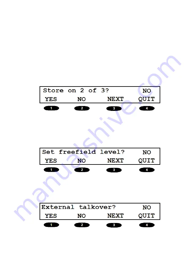
Siemens SD 270 Operating Manual Download Page 19

19

Store on 2 of 3?:

Automatically stores a threshold if the 
responses made to two out of three 
test signals are at the same hearing 
level.

Set freefield levels?:

This option provides access to the  
freefield calibration function; refer to 
Appendix 2 for details.

External Talkover?:

Select NO to use the internal micro-
phone and YES to use the MIC 1 input.

Summary of Contents for SD 270

Page 1: ...Operating Manual Applies from Serial Number 8200 onwards SD 270 Diagnostic Audiometer ...

Page 2: ...Overview of SD 270 Audiometer Controls ...

Page 3: ...diometer connections 11 2 5 Data transfer to a printer 12 2 6 Data transfer to a computer 13 2 7 Line in out connection audio 13 3 Using the Audiometer 14 3 1 Ambient conditions 14 3 2 Switching the audiometer on and off 14 3 3 Operating language 14 3 4 Testing the patient response switch 15 3 5 Audiometer display 15 3 6 Audiometer controls 15 3 7 Threshold Retention Function 30 3 8 Uncomfortable ...

Page 4: ...8 3 Mains adapter maintenance 45 8 4 Perform listening check 45 9 Instrument Storage and Transportation 46 10 Calibration Return of the Instrument 47 11 Guarantee 48 12 Ordering Consumables Accessories 49 Appendix 1 Speech Audiometry 50 Headphone and Free Field Testing 50 Operator Monitoring 50 Test Modes in Speech Audiometry 51 Display Counter 51 1 Live Voice Speech Audiometry to Headphones 52 2 ...

Page 5: ...rded 59 Appendix 2 Free Field Calibration Procedure 60 1 Assurance Of Calibration 60 2 External Amplifier and Loudspeaker 60 3 Calibration Overview 60 4 Free field Speech Calibration 61 5 Free field Warble Tones Calibration 64 6 Free field Live Speech Calibration 67 Appendix 3 EMC Guidance Manufacturer s Declaration 68 Appendix 4 Use with Non medical Electrical Equipment 74 Appendix 5 Technical Su...

Page 6: ...output from the headphones in speech mode and a range of clinical audiometry tests 1 2 Unpacking Open the shipping carton and carefully remove all the equipment Check against the delivery note that all the accessories ordered have been included with your audiometer If anything is missing please contact your local Service department see Appendix 5 If you have purchased from a distributor you should...

Page 7: ... cable Insert earphones Data cable for NOAH Link driver disk for NOAH 1 5 Frequently used functions How to switch on off or set the language or control the level Please refer to section 3 of this instruction 1 6 Known contradictions There are no contradictions known for the use and application of the SD 270 Audiometer ...

Page 8: ... only with the medically approved mains adapter supplied which is specified as part of the equipment Do not use any other type of mains adapter with this instrument Refer to Section 12 for the stock number of the adapter The audiometer is for indoor use only and should be used only as described in this manual The transducers supplied with the audiometer are specifically calibrated with it if these...

Page 9: ...servicing requirements Opening the instrument will void the warranty 2 2 Electromagnetic compatibility EMC considerations Medical electrical equipment needs special precautions regarding EMC and needs to be installed and put into service according to the EMC information provided in Appendix 3 This provides guidance on the electromagnetic environment in which to operate the instrument Portable and ...

Page 10: ...s fitted with electronic circuit protection In case of overload the adapter will shut down and the indicator will be extinguished When the fault is cleared the adapter will operate as normal The input is to the mains adapter is protected with a non replacea ble fuse If this fails the adapter will not operate The mains adapter is the mains disconnect device and therefore the audiometer should be po...

Page 11: ...rophone MONITOR 3 5mm jack Monitor Earphone BONE 6 3mm jack Grey Bone Vibrator Headset INSERT 3 5mm jack Masking Earphone RIGHT LEFT 6 3mm jack 6 3mm jack Red Blue Air conduction headset MIC 2 3 5mm jack Talkback Microphone POWER 2 5mm power jack Mains AC DC Adapter RESPONSE 6 3mm jack Black Patient Response Switch LINE IN LINE OUT 3 5mm jack 3 5mm jack CD tape player External amplifier See 2 7 DA...

Page 12: ...ndix 4 2 5 Data transfer to a printer Safety Note Please refer to Appendix 4 for important information regar ding the connection of non medical electrical equipment to medical electrical equipment The audiometer can be upgraded with an option to allow connection to a designated portable thermal printer for printing air conduction bone conduction speech and ULL test results see 3 11 You must use th...

Page 13: ...ied with this option 2 7 Line in out connection audio Safety Note Please refer to Appendix 4 for important information regar ding the connection of non medical electrical equipment to medical electrical equipment The Siemens SD 270 has audio line in out connections for CD or tape player input e g for recorded speech testing and amplifier output Important Note Line out connections are switched on o...

Page 14: ...ther press the key under OK on the display to confirm the current headphone selection f Or press the key under CHANGE to toggle to the other option and then OK to confirm the selection Important Note The headphone selection must be confirmed before any other operation can be performed The display will then be as shown in 3 5 f To switch off press the key again and then the key under YES to confirm...

Page 15: ...g This indicates that when the PRESENT key is pressed the tone presented will be at 30dBHL at a frequency of 1kHz 1000 Hz to the designated ear Please note that on start up the audiometer defaults to the left ear 3 6 Audiometer controls 3 6 1 SoftKeys Four softkeys are provided below the display that may refer to an associated option shown on the display In this operating manual these are referenc...

Page 16: ...modify the settings as required Pressing the softkey below QUIT exits the options menu and saves the settings Menu Option Description Clear test Clears all displayed test results if the YES key is pressed stored test results are not affected Save audiogram to 1 Use UP key to select intended storage location and press SAVE key to save test results ...

Page 17: ...lect the required sto rage location and press LOAD key to retrieve test results Contrast Adjust using the UP and DOWN keys Bone masking Selects the headset or the optional masking earpiece as the means of mas king select Insert or Phones key ...

Page 18: ...e is enabled use Softkeys 1 or 2 to select the required headphone type FF equiv speech This option is only available if eit her DD45 or TDH39 is the selected headphone if activated free field equivalent levels will output to the headphone in speech mode refer to Appendix 1 ...

Page 19: ...e to two out of three test signals are at the same hearing level Set freefield levels This option provides access to the freefield calibration function refer to Appendix 2 for details External Talkover Select NO to use the internal micro phone and YES to use the MIC 1 input ...

Page 20: ...20 Display Counter Activates a percentage counter for use with speech testing refer to Appendix 1 Omit 750 1k5 3k 6k To exclude these frequencies from those available for testing press the YES key ...

Page 21: ...e minimum and maximum times that a stimulus can sound when the PRESENT key is pressed either 0 5 sec min 10sec max or 1 0 sec min 2 0 sec max FF Speech units The units for freefield speech may be switched between dBHL and dBSPL ...

Page 22: ...reen SPEECH Selects speech mode the indicator above the key illuminates green refer to Appendix 1 for details note that initially only Softkeys 1 3 have a function MASK Switches on masking at 30dBHL narrow band for pure tones or speech weighted masking the indicators above the key and to the right of the display illuminate green for speech mode use Softkey 4 to select INT for internally genera ted...

Page 23: ... used to show that the function is active and an additio nal display message indicates levels greater than 100dBHL Important Note This function will not operate if continuous tone presentation has been enabled LOCK Synchronous masking function Locks signal and mask output at a constant difference when the SIGNAL control is adjusted An indicator above the key illuminates green when active The MASK ...

Page 24: ... the frequency PRESENT Press to present the displayed test signal to the test subject The Present indicator to the left of the display will be illuminated green during tone presentation TALKOVER Interrupts test and routes operator s voice from the internal microphone or MIC 1 input to headset The attenuation level can be adjusted with the SIGNAL rotary control ...

Page 25: ... output Press the key again to de select The talkback level may be adjusted by the SIGNAL control while key is held down PRINT Press to print audiogram see Section 3 11 for further details dB STEP Enables the operator to set 2 5dB as the default step size In case 2 5dB step size is not selected 5 dB step size is taken as default ...

Page 26: ...or to select the required out put transducers In case only DD45 headphone is installed the display will show the message Only one set available Push Softkey 4 to quit the screen STORE Saves the displayed combination of frequency attenuation and ear as a threshold retention value Please see section 3 7 for further details ...

Page 27: ...ressing the TEST MENU key again Menu Option Description STENG Stenger Routes tone or speech to both ear phones simultaneously Use the SIGNAL rotary control to adjust the Left channel level and the MASK rotary control to adjust the right Refer to Appendix 1 for details of the Stenger test in speech mode ...

Page 28: ...key interrupts the signal presented SISI Short Increment Sensitivity Index Presents a tone continuously at the level and frequency dis played Pressing the PRESENT key increases the level by the increment shown on the lower line of the display Change this increment by using the UP DOWN softkeys Softkey 4 switches bet ween the initial display and a counter that logs and displays the results of the t...

Page 29: ...29 Use Softkey 1 to record a response Use Softkey 2 to record no response Use Softkey 3 to clear the results display Use Softkey 4 to return to the initial SISI display ...

Page 30: ...and record them on an audiogram card print with the optional printer and or transfer results to a NOAH database on a computer f f To review the retained threshold select the frequency using Hz frequency keys The stored value for the left ear desi gnated L and the stored value for the right ear designated R are shown on the lower line of the display The display shows thresholds at 4kHz Left ear 20d...

Page 31: ... to 12 audiograms referenced by number in the internal memory of the audiometer To save the current set of audiogram thresholds press the OPTIONS key press the NEXT key repeatedly until Save Audiogram to appears on screen Use the UP key to select a location numbered 1 12 then press the SAVE key Any results for ULL thresholds or speech testing see Appendix 1 will also be saved Note that the Save pr...

Page 32: ... Connect the audiometer to the printer with supplied printer cable refer to Section 2 5 of this operating manual for printer set up Insert the 6 pin mini DIN into the DATA socket on the back of the audiometer Insert the terminal plug into the socket at the back of the printer Ensure the printer is switched on and ready to print Load the desired audiogram as described in 3 10 to print the current a...

Page 33: ... transfer of test results stored within the audiometer to a NOAH database you will need the Siemens link driver disc stock number 105 98 699 This option includes a USB cable to connect to a PC and the necessary installation operating instructions ...

Page 34: ...o the patient As soon as you hear the tone press the response switch When you no longer hear the tone release the response switch 6 Select the better hearing ear according to the patient by pressing either the LEFT or RIGHT key 4 2 Test 7 Present the first test tone at 30dB at 1kHz 8 If the patient responds reduce the signal level in 10dB steps until they no longer respond then increase the signal...

Page 35: ...responded 2 out of a maximum of 3 times at the same si gnal level this will automatically display the threshold on the screen 14 Proceed to the next test frequency and repeat steps 7 to 13 15 Repeat steps 7 to 14 for the other ear 4 3 Post test 16 Use the Threshold Retention Function to review the results See 3 6 If required do one or more of the following f f Record the results on an audiogram ca...

Page 36: ...kHz Output level accuracy Within 3dB Output level step size 2 5 or 5dB Output transducer AC DD45 earphones supplied E 5A insert earphones option Output transducer BC B 71 bone vibrator supplied Tone present Single pulsed warble or continuous Masking Narrowband or broadband Lock Synchronous channel lock Clinical tests SISI Stenger ABLB Communication Integral talk over and talk back facility Recorde...

Page 37: ... 750 120 65 1000 120 70 1500 120 70 2000 120 70 3000 120 70 4000 115 70 6000 110 50 8000 100 40 5 3 Physical Data Display 2 lines of 24 characters Mains Power 100 240 Vac 50 60Hz 0 25A Dimensions 355mm long x 230mm deep x 100mm high Weight 1 6kg Safety IEC 60601 1 plus UL CSA EN deviations EMC IEC 60601 1 2 CE mark To the EU Medical Device Directive ...

Page 38: ... electric shock Type B applied part Degree of protection against ingress Not protected of water Mode of operation Continuous operation Equipment mobility Portable The SD 270 Audiometer is classified as a Class IIa device under Annex IX Section 1 of the EU Medical Devices Directive It is intended for use as a diagnostic audiometer instrument ...

Page 39: ... left right earphones bone vibrator insert masker patient response switch and the associated cables Definition The output from the Mains AC adaptor is Direct Current Definition Class II equipment equipment in which protection against electric shock does not rely on BASIC INSULATION only but in which additional safety pre cautions such as DOUBLE INSULATION or REINFORCED INSULATION are provided ther...

Page 40: ...le Modulating frequency 15 625Hz Frequency deviation 10 Speech Channel Frequency response 3dB from 100Hz to 10kHz electrical Input voltage requirement at default level to zero meter 600mVrms at 1kHz Output level 90dBSPL at 1kHz for attenuator set ting of 70dBHL with level meter at 0dB Masking Sounds Masking sounds available Narrow bands at test frequencies and Speech weighted noise NB noise bandwi...

Page 41: ...d For mastoid placement Sound attenuation characteristics ISO8253 1 Table 3 Airborne sound from bone vibrator See Br J Audiol 1980 P73 75 Environmental Operating temperature 15 C to 35 C Operating humidity 30 to 90 non condensing Atmospheric pressure 700 hPa to 1060 hPa Input Output Power input 2 5mm barrel type socket Mic inputs impedance 2500 Ohms Mic inputs connection Mono 3 5mm Jack socket Lin...

Page 42: ...ient response input 6 3mm Jack socket Left Right Bone outputs 6 3mm Jack socket Monitor output Mono 3 5mm Jack socket Insert output Mono 3 5mm Jack socket USB Type B socket Max voltage at any output 12V peak ...

Page 43: ... local Service department see Annexx 5 requesting the relevant part number see Section 12 Handle the audiometric headset bone vibrator headset and other accessories with care For parts that are in direct contact with the patient it is recommended that replacement parts are used or the parts are subjected to a standard disinfecting procedure between patients This includes physically cleaning and us...

Page 44: ...t is each eartip is in tended to be used once only for a single ear for a single patient Do not reuse eartips as this will pose the risk of ear to ear or patient to patient cross infection Further guidance is provided below f f Ensure that the black tubing protruding the foam eartip is not applied to the patient this must be attached to the sound tube of the insert transducer f f Roll the foam ear...

Page 45: ...stening check Important Note It is strongly recommended to check the proper function and calibration of the signal levels on a regular base The listening check can be done by testing the own hearing abi lity and compare the results to a reference In case deviations are found the instrument shall not be further used for patient testing until a new calibration has been applied see section 10 It is r...

Page 46: ... and Transportation Please note that this instrument can be stored or transported with the following environmental parameters Temperature 20 C to 70 C Humidity 10 to 90 non condensing Atmospheric Pressure 500 hPa to 1060 hPa ...

Page 47: ...of calibration services see Appendix 5 Important Note The instrument should be returned to the manufacturer for service repair There are no user serviceable parts within it When packing the instrument for shipping please use the original shipping carton and packing materials Please also ensure that the headset leads are not wrapped around the headband of the head set ...

Page 48: ...te of despatch if re turned carriage paid to one of the service departments listed in Annexx 5 Important Note The following exeptions apply Earphones bone vibrator and other transducers may go out of calibration due to rough handling or impact dropping The life of the leads is also dependent upon conditions of use These parts are only guaranteed against faulty materials or manufacture ...

Page 49: ...ent response switch 105 98 698 Audiogram cards pack of 50 104 26 135 Siemens SD 270 operating manual 106 00 113 Microphone and monitor headset 106 00 114 Insert masker 100 55 806 Insert earphones 106 00 115 6 pin printer cable for audiometer to printer 105 98 699 Siemens link driver disk NOAH incl USB type B cable 106 00 116 Printer Able AP1300 106 00 117 Thermal printer paper for Able AP1300 Impo...

Page 50: ...nded that any attached amplifier should switched off If Free Field testing is being performed this option must always be selected on the audiometer this disconnects headphones bone vibrator and masking insert outputs and ensures that the correct calibrated output levels are achieved Free field equivalent output is available from the headphones in Speech mode see Section 3 6 of this operating manua...

Page 51: ... again returns to the original speech mode Display Counter The Display Counter is available only in Speech mode Use Softkey 3 to activate the counter For any given level of stimulus the display then shows the percentage correct alongside the total number of responses To use the counter the operator selects YES or NO according to the response made by the patient Pressing Softkey 3 clears the counte...

Page 52: ...f f Input signal adjustment should be made to adjust for the operator s voice to peak at the 0dB point on the LEVEL dB bar graph the earphone output will then be 89dBSPL for a SIGNAL setting of 70 dBHL and 1kHz puretone into an IEC 318 ear simu lator f f The output level is controlled in 5dB steps by the SIGNAL control 1 2 Procedure The operator may now read the required word list to the subject a...

Page 53: ...ing is now routed to the opposite earphone to that selected f f The MASK rotary control changes the masking level in 5dB steps f f If required readjustment of the input signal level can be accessed by temporarily deselecting the MASK key then proceed as in 1 1d 2 2 Procedure As described in 1 2 but adjusting the masking level as required ...

Page 54: ...o the left earphone To select the right earphone press RIGHT f f The input signal is adjusted in 1dB steps by use of the MASK rotary control f f Play the 1kHz calibration tone on the recorded material and adjust the input signal such that the LEVEL dB bar graph reads 0dB the headphone output measured in an IEC 318 ear simulator will now be 89dBSPL for a setting of 70 dBHL f f The output level is c...

Page 55: ...ource using Softkey 4 the option selected is displayed in capitals internal will be wideband noise and external will be the competing noise from the signal source f f The MASK rotary control changes the masking level in 5dB steps f f If required readjustment of the input signal level can be accessed by temporarily deselecting the MASK key then proceed as in 3 1d 4 2 Procedure As described in 3 2 b...

Page 56: ... f Connect an external amplifier speaker to the LINE OUT jack socket refer to Section 2 7 of this operating manual f f Connect a microphone to the MIC1 input on the audiometer f f Press SPEECH FREEFIELD and use Softkey 1 to ensure that MIC is displayed in capitals indicating that the external microphone is selected f f The external microphone is now routed to the external amplifier and speaker use...

Page 57: ... LINE is displayed in capitals indicating that the line input is selected f f The line input is now routed to the external amplifier and speaker use LEFT and RIGHT to select the required amplifier channel f f Play the 1kHz calibration tone on the recorded material and follow the calibration procedure in Appendix 2 f f The input signal is adjusted in 1dB steps by use of the MASK rotary control f f ...

Page 58: ...ct MASK f f Select internal masking source using Softkey 4 the INT option is displayed in capitals wideband noise is routed to the competing LINE OUT channel f f The level of competing noise is adjusted in 5db steps using the MASK rotary control 7 2 Procedure As described in 3 2 but adjusting the competing noise level as required ...

Page 59: ...rce using Softkey 4 the EXT option is displayed in capitals competing noise from the signal source is routed to the competing LINE OUT channel f f Use the SIGNAL rotary control to adjust the signal channel and MASK rotary control to adjust the noise channel 8 2 Procedure As described in 3 2 but adjusting the competing noise level al required ...

Page 60: ...required calibration equipment operating procedures and trained technical staff are available to perform this operation Once calibrated items should not be moved removed or added to the room without re calibration 2 External Amplifier and Loudspeaker The following external equipment is specified for use of the Siemens SD 270 audiometer in free field modes of operation Amplifier Interacoustics AP70...

Page 61: ...equired later and a speech calibration is performed this will invalidate any previous warble calibration which would then need to be repeated If warble tones are to be used as a means of equalising the frequency response in the spee ch calibration see Section 4 1 1 of this appendix then this will in validate any previous warble calibration which would then need to be repeated when warble tone test...

Page 62: ...control to set the output to 70dBHL and adjust the external amplifier to give a reading of 90dBSPL as measured by the SLM at the reference point The response should then be checked to be within the following limits IEC 60645 2 1993 Section 10 1 Frequency Range Hz Tolerance dB 125 to 250 0 10 250 to 4000 3 3 4000 to 6300 5 5 If necessary adjustments should be made using the amplifier con trols or a...

Page 63: ...easure the actual listening point level for when playing the calibration tone of each alternative set of test recordings For each alternative set of test recordings produce a correction table the difference between the actual listening point level measured and 90dBSPL Apply this correction to the output level of the audiometer while conducting a test to compensate for the minor difference in calib...

Page 64: ...nes The audiometer will now output 70dBHL from the Left channel As reference for the calibration of warble tone sound pressure levels the values from ISO 389 7 Table 1 are used binaural on axis Freq Hz 125 250 500 750 1k 1k5 2k 3k 4k 6k 8k dB SPL 92 81 74 72 72 70 5 68 5 64 63 5 72 5 81 5 If a calibration of the speech channel has already been carried out Adjust the calibration level for the 1kHz ...

Page 65: ...e until all frequencies have been calibrated for the Left channel To calibrate the Right channel if required press the RIGHT key do not change the amplifier s volume control Adjust the calibration for all of the right channel frequencies including 1000Hz by using the Hz keys and the SIGNAL control as described above To store the levels and leave Free field calibration mode press the STORE key If r...

Page 66: ...ch calibration is not required Enter the Free field calibration mode as described in A2 5 1 Press the SPEECH key and the display will change to indicate the option to adjust the competing noise calibration level the legend Sp Mask is used to indicate this Without changing the setting on the external amplifier use the SIGNAL control to adjust the level of the competing noise to 90dBSPL as measured ...

Page 67: ...d in capitals indicating that the external microphone is selected The input signal is adjusted in 1dB steps with the MASK rotary control Input signal adjustment should be made to adjust for the operator s voice to peak at the 0dB point on the LEVEL dB bar graph If recorded speech has been calibrated no further action is necessary If recorded speech has not been calibrated the volume control of the...

Page 68: ... guidance RF emissions CISPR 11 Group 1 SD 270 Audiometer uses RF en ergy only for its internal func tion Therefore its RF emissions are very low and are not likely to cause interference in nearby electronic equipment RF emissions CISPR 11 Class A The SD 270 Audiometer is suita ble for use in all establishments other than domestic and those directly connected to the pu blic low voltage power suppl...

Page 69: ...ontact 8 kV air 6 kV contact 8 kV air Floors should be wood concrete or ceramic tile If floors are covered with synthetic ma terial the relative humidity should be at least 30 Electrical fast transient burst IEC 61000 4 4 2 kV for power supply lines 1 kV for input output lines 2 kV for power supply lines 1kV for input output lines Mains power qua lity should be that of a typical com mercial or hos...

Page 70: ... cycles 5 UT 95 dip in UT for 5 sec Mains power quality should be that of a typi cal commercial or hos pital environment If the user of the SD 270 Audi ometer requires continu ed operation during po wer mains interruptions it is recommended that the SD 270 Audiometer be powered from an uninterruptible power supply or a battery Power frequen cy 50 60 Hz magnetic field IEC 61000 4 8 3 A m 3 A m Powe...

Page 71: ...ions equipment should be used no closer to any part of the SD 270 Audiometer including cables than the recommended separation distance calculated from the equation applicable to the frequency of the transmitter Recommended separation di stance Conducted RF IEC 61000 4 6 3 Vrms 150kHz to 80MHz 3 Vrms d 1 2 P Radiated RF IEC 61000 4 3 3 V m 80MHz to 2 5GHz 3 V m d 1 2 P 80MHz to 800MHz d 2 3 P 800MH...

Page 72: ...from fixed transmitters such as base stations for radio cellular cordless telephones and land mobile radios amateur radio AM and FM radio broadcast and TV broadcast cannot be predicted theoretically with accuracy To assess the electromagnetic environ ment due to fixed RF transmitters an electromagnetic site survey should be considered If the measured field strength in the location in which the SD ...

Page 73: ...ns mitter W Separation distance according to frequency of transmitter m 150 kHz to 80 MHz d 1 2 P 80 MHz to 800 MHz d 1 2 P 800 MHz to 2 5 GHz d 2 3 P 0 01 0 12 0 12 0 23 0 1 0 38 0 38 0 73 1 1 2 1 2 2 3 10 3 8 3 8 7 3 100 12 12 23 For transmitters rated at a maximum output power not listed above the recommended separation distance d in metres m can be estimated using the equation applicable to th...

Page 74: ...pecial precautions must be taken in order to maintain medical safety The following notes are provided for gui dance in making such connections to ensure that the general requi rements of clause 16 of IEC 60601 1 2005 are met The following signal inputs and outputs on the SD 270 audiometer are electrically isolated to the requirements of IEC 60601 1 in order to reduce any potential hazard associate...

Page 75: ... 60601 series for medical electrical equipment Equipment not complying with IEC 60601 shall be kept outside the patient environment as defined in IEC 60601 1 at least 1 5m from the patient The operator must not touch the connected equipment and the patient at the same time as this would result in an unacceptable hazard Please refer to Diagrams 1 to 5 below for typical configurations of connected p...

Page 76: ...76 Diagram 1 SD 270 used with the medically approved mains adapter Mains Outlet Medical Mains Adapter SD 270 Audiometer ...

Page 77: ...77 Diagram 2 SD 270 used with the medically approved mains adapter and printer Mains Outlet Medical Mains Adapter SD 270 Audiometer Mains Outlet Printer Power Supply Printer via DATA socket ...

Page 78: ...78 Diagram 3 SD 270 used with the medically approved mains adapter and PC Mains Outlet Medical Mains Adapter SD 270 Audiometer Mains Outlet PC Power Supply PC via USB socket ...

Page 79: ...79 Diagram 4 SD 270 used with the medically approved mains adapter and CD Tape player Mains Outlet Medical Mains Adapter SD 270 Audiometer Mains Outlet CD Tape Player via Line In Socket ...

Page 80: ...80 Diagram 5 SD 270 used with the medically approved mains adapter and external amplifier Mains Outlet Medical Mains Adapter SD 270 Audiometer Mains Outlet Amplifier via Line Out Socket ...

Page 81: ...9131 308 33 33 E mail connexx sivantos com Internet www bestsound technology de France Phone 01 49 33 15 15 puis taper 3 Internet www bestsound technology fr South East Asia Phone 65 63 70 96 66 E mail sm customerservice smi sivantos com Internet www bestsound technology com sg UK Ireland Technical Support Phone 01293 423671 E mail servicedesk sivantos com Internet www bestsound technology co uk ...

Page 82: ...82 Australia New Zealand Phone 0011 61 7 3858 7700 E mail techsupport shia sivantos com Internet www bestsound technology co au ...

Page 83: ... Ltd Hearing Instruments Newton Road Crawley RH10 9TT Deutschland Sivantos GmbH Henri Dunant Strasse 100 91058 Erlangen France Sivantos S A S 175 Bd Anatole France BP40 93201 Saint Denis Cedex 1 Acoustic Technologies Ltd Unit 5a Howth Junction Business Center Kilbarrack Dublin 5 www akoustic net With the CE marking Sivantos GmbH confirms compliance with the European Directive 93 42 EEC concerning ...

Page 84: ...ation in this document contains general descriptions of the technical options available which do not always have to be present in individual cases and are subject to change without prior notice The required features should therefore be specified in each individual case at the time of conclusion of the respective contract Manufactured by Sivantos GmbH under Trademark License of Siemens AG ...

Reviews: