RWD45U Controller Installation and Commissioning Guide
Document Number 129-409
October 5, 2009
Siemens Industry, Inc.
Page 3 of 13
NOTE:
Three-stage applications are also used for one- and two-stage applications. Compressor stages are
selected during commissioning.
Example: Two-stage compressor with reversing valve on heating, economy cooling, and two averaging
sensors:
#35
.
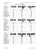
Table 2. Input Configurations – X1, X2, X3 and D1.
Applications 10 Through 69
X1
X2
X3
D1 Options
Filter
Alarm
Alarm
Day/Night
Standby
#x0 (Standby)
Main
Standby
Eco
♦
♦
♦
–
#x1 (Remote
setpoint)
Main
Remote setpoint
Eco
♦
♦
♦
♦
#x2 (Alarm)
Main
Alarm
Eco
♦
–
♦
♦
#x3 (Filter alarm)
Main
Filter alarm
Eco
–
♦
♦
♦
#14, 24, 34 (Setpoint
Reset) *
Main
Setpoint reset +
Eco (cool)
Standby
♦
♦
♦
–
#44, 54, 64 (Setpoint
Reset)
Main
Setpoint reset
Eco
(heat)
♦
♦
♦
♦
#x5 (Avg. X1, X2)
Main
Main
Eco
♦
♦
♦
♦
#x6 (Win/Sum
Digital)
N/A
N/A
N/A
–
–
–
–
#x7 (Win/Sum
Analog)
N/A
N/A
N/A
–
–
–
–
#x8 (Sensor select)
Main Main
Eco
♦
♦
♦
♦
#x9 (Active input)
Main
Standby
Eco
♦
♦
♦
–
* For applications 14, 24, and 34, the X2 sensor (outside air temperature) is used for both economizer and setpoint reset
shift.
Applications 70 Through 99
X1
X2
X3
D1 Options
Filter
Alarm
Alarm
Day/Night
Standby
#x0 (Standby)
Main
Standby
Ind
♦
♦
♦
–
#x1 (Remote
setpoint)
Main
Remote setpoint
Ind
♦
♦
♦
♦
#x2 (Alarm)
Main
Alarm
Ind
♦
–
♦
♦
#x3 (Filter alarm)
Main
Filter alarm
Ind
–
♦
♦
♦
#x4 (Setpoint reset)
Main
Setpoint reset
Ind
♦
♦
♦
♦
#x5 (Avg. X1, X2)
Main
Main
Ind
♦
♦
♦
♦
#x6 (Win/Sum
Digital)
Main
Win/Sum digital
Ind
♦
♦
♦
♦
#x7 (Win/Sum
Analog)
Main
Win/Sum analog
Ind
♦
♦
♦
♦
#x8 (Sensor select)
Main Main
Ind
♦
♦
♦
♦
#x9 (Active input)
Main
Standby
Ind
♦
♦
♦
–

