background image

Document Number 129-409 

RWD45U Controller Installation and Commissioning Guide 

October 5, 2009 

Page 

10 of 13


Siemens Industry, Inc.


+


Main Display to PS Mode 

Press both                   buttons, and hold for five seconds to enter the PS mode. PS4 will appear 
first. 

 
Press the  

     button to scroll down to the right PS for editing parameters. 


Software Tool 
(Optional 
Commissioning)


A software tool for the controller application selection and parameter adjustment is 
available. It is a user-friendly Windows® 95 (or later) based software tool. The software 
tool has the following functions: 

Adjusting all available parameters. 
Uploading and downloading the program. 
Saving parameter settings. 
Viewing or providing a print-out of the settings. 
Parameters can be hidden from displaying.


Commissioning 
Flowchart 


Figure 3.  Commissioning Flowchart. 

Summary of Contents for RWD45U

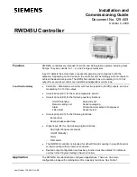
Page 1: ...dulating 0 to 10 Vdc output Universal input X1 for the main temperature sensor Universal input X2 for the following auxiliary functions On Off Standby Setpoint reset Remote setting unit Sensor averaging Alarm Winter Summer setpoint changeover Filter alarm Sensor select Universal input X3 for the following functions Economizer Second independent loop Digital input D1 for the following digital funct...

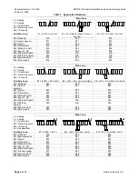
Page 2: ... Cr Compressor RV Reversing valve Eco Economy Main Loop RV RV Auxiliary Loop 4 2H2C Eco Heat 5 3Cr RV cool Eco Heat 6 3Cr RV Heat Eco Heat x0 Standby 40 50 60 x1 Remote setpoint 41 51 61 x2 Alarm 42 52 62 x3 Filter alarm 43 53 63 x4 Setpoint reset 44 54 64 x5 Avg X1 X2 45 55 65 x6 Win Sum Digital N A N A N A x7 Win Sum Analog N A N A N A x8 Sensor select 48 58 68 x9 Active input 49 59 69 H Heating...

Page 3: ...co 14 24 34 Setpoint Reset Main Setpoint reset Eco cool Standby 44 54 64 Setpoint Reset Main Setpoint reset Eco heat x5 Avg X1 X2 Main Main Eco x6 Win Sum Digital N A N A N A x7 Win Sum Analog N A N A N A x8 Sensor select Main Main Eco x9 Active input Main Standby Eco For applications 14 24 and 34 the X2 sensor outside air temperature is used for both economizer and setpoint reset shift Applicatio...

Page 4: ...g Stage 2 C2 Eco Cool 40 through 49 Eco Heat 70 through 79 Ind Application Numbers Q1 Q2 Q3 Q4 Y1 20 through 29 Reversing Valve RV Cool Compressor Stage 1 Cr1 Compressor Stage 2 Cr2 Compressor Stage 3 Cr3 Eco Cool 30 through 39 Reversing Valve RV Heat 50 through 59 Reversing Valve RV Cool Eco Heat 60 through 69 Reversing Valve RV Heat 80 through 89 Reversing Valve RV Cool Ind 90 through 99 Reversi...

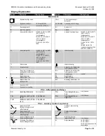
Page 5: ...s cooling C Celsius scale Indicates heating F Fahrenheit scale SP h Setpoint on the heating side for temperature control No unit e g pressure air quality and air volume flow SP c Setpoint on the cooling side for temperature control K Kelvin Y1 Analog output 0 to 10V Percentage scale Q Digital outputs Output status Off ECO Economy mode Output status On R V Reversing valve status On Standby mode OFF...

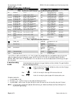
Page 6: ... sensor 0 to 10 Vdc 100 to 2400 X3H Stop point of the X3 for 0 to 10 Vdc only 100 to 2400 X3 0 10 X3 is 0 to 10 Vdc input sensor 0 to 10 Vdc 100 to 2400 X2SP Remote setpoint 0 to 10 Vdc or 0 to 1000 Ω X3 If X3 is independent control C F no unit display X1 0 to 50 C Y1 0 to 10 Vdc X2VR Variable Resistor 0 to 1000 Ω PS 1 Application Number Selection Standby mode AVERAGE Averaging sensor X1 and X2 RE...

Page 7: ...Pt1000 0 to 10 Vdc Ni1000 Enter X2 sensor calibration offset Ni or Pt only 5 K 0 K Enter X2 active sensor range 0 to 10 Vdc only 100 to 2400 32 F to 122 F 0 C to 50 C Select sensor X3 for Economizer sensor Ni1000 Pt1000 0 to 10 Vdc Ni1000 Enter X3 sensor calibration offset Ni or Pt only 5 K 0 K Enter X3 active sensor range 0 to 10 Vdc only 100 to 2400 32 F to 122 F 0 C to 50 C Select unit for X3 f...

Page 8: ... 1 2 and 3 0 to 4 096 s 0 s Enter min Off time for output stage 1 2 and 3 0 to 4 096 s 60 s Enter time delay TD for next stage On 0 to 4 096 s 30 s Enter changeover time delay TD heating cooling demand 0 to 4 096 s 120 s Setpoint Mode Range Type Default Enter SP h1 Sensor range 70 F 21 C Enter SP h2 Sensor range 68 F 20 C Enter SP h3 Sensor range 66 F 19 C Enter SP c1 Sensor range 73 F 23 C Enter ...

Page 9: ...hanging Setpoint in Main Display On entering any of the setpoint displays the setpoint on display can be adjusted by pushing the SEL λ button Increase value by pressing the button or decrease the value by pressing the button When the required value is reached press the SEL λ button to save the new value Time out For setpoint adjustment during normal operation the controller will exit the setting a...

Page 10: ...ng parameters Software Tool Optional Commissioning A software tool for the controller application selection and parameter adjustment is available It is a user friendly Windows 95 or later based software tool The software tool has the following functions Adjusting all available parameters Uploading and downloading the program Saving parameter settings Viewing or providing a print out of the setting...

Page 11: ...1 Compressor stage 2 Compressor stage 3 Reversing valve relay Equipment with 0 to 10 Vdc input Damper actuators Room temperature sensor Auxiliary sensor or a digital input Economy or 2nd loop sensor Switch or time clock Personal computer For a single compressor CR2 and CR3 are not connected For a dual compressor CR3 is not connected Figure 5 Applications 20 through 39 50 through 69 and 80 through ...

Page 12: ...re tightened before final mounting to front panel D Inside the ARG62 21 WARNING There must be a minimum of 0 31 inches 8 mm distance from terminations to panel enclosures to avoid electric shock Electrical Installation Notes Standard cables can be used for the controller However when mounting in an environment greatly exposed to EMI use only shielded cables The RWD45U is designed for 24 Vac operat...

Page 13: ... product or company names mentioned herein may be the trademarks of their respective owners 2009 Siemens Industry Inc Siemens Industry Inc Building Technologies Division 1000 Deerfield Parkway Buffalo Grove IL 60089 1 847 215 1000 Your feedback is important to us If you have comments about this document please send them to SBT_technical editor us sbt siemens com Document No 129 409 Printed in the ...

Reviews: