background image


Preface

RUGGEDCOM WIN5137-V

Installation Guide

vi

Related Documents

Related Documents

Other documents that may be of interest include:

RUGGEDCOM SU User Guide

 [https://support.industry.siemens.com/cs/ww/en/view/109737453]

Training

Siemens offers a wide range of educational services ranging from in-house training of standard courses on

networking, Ethernet switches and routers, to on-site customized courses tailored to the customer's needs,

experience and application.
Siemens' Educational Services team thrives on providing our customers with the essential practical skills to make

sure users have the right knowledge and expertise to understand the various technologies associated with critical

communications network infrastructure technologies.
Siemens' unique mix of IT/Telecommunications expertise combined with domain knowledge in the utility,

transportation and industrial markets, allows Siemens to provide training specific to the customer's application.
For more information about training services and course availability, visit 

https://www.siemens.com/ruggedcom

 or

contact a Siemens Sales representative.

Customer Support

Customer support is available 24 hours, 7 days a week for all Siemens customers. For technical support or general

information, contact Siemens Customer Support through any of the following methods:

Online

Visit 

http://www.siemens.com/automation/support-request

 to submit a Support Request (SR) or check

on the status of an existing SR.

Telephone

Call a local hotline center to submit a Support Request (SR). To locate a local hotline center, visit 

http://

www.automation.siemens.com/mcms/aspa-db/en/automation-technology/Pages/default.aspx

.

Mobile App

Install the Industry Online Support app by Siemens AG on any Android, Apple iOS or Windows mobile

device and be able to:
• Access Siemens' extensive library of support documentation, including FAQs and manuals
• Submit SRs or check on the status of an existing SR
• Contact a local Siemens representative from Sales, Technical Support, Training, etc.
• Ask questions or share knowledge with fellow Siemens customers and the support community

Summary of Contents for RUGGEDCOM WIN5137-V

Page 1: ...RUGGEDCOM WIN5137 V Installation Guide 11 2018 RC1265 EN 04 Preface Introduction 1 Installing the Subscriber Unit 2 Device Management 3 Technical Specifications 4 Certification 5 ...

Page 2: ... that you regularly check for product updates For the secure operation of Siemens products and solutions it is necessary to take suitable preventive action e g cell protection concept and integrate each component into a holistic state of the art industrial security concept Third party products that may be in use should also be considered For more information about industrial security visit https w...

Page 3: ...er Unit 7 2 3 Site Preparation and Precautions 7 2 4 Mounting the Subscriber Unit 8 2 4 1 Mounting the Subscriber Unit to a Wall or Tower 9 2 4 2 Mounting the Subscriber Unit to a Pole 10 2 5 Installing the Antennas 12 2 6 Grounding the Subscriber Unit 13 2 7 Connecting Power and Data 14 2 8 Weatherproofing the Subscriber Unit 14 2 8 1 Weatherproofing a Cable 15 2 8 2 Applying Cold Shrink Tubing 1...

Page 4: ...dem Specifications 19 4 4 Operating Environment 20 4 5 Mechanical Specifications 20 4 6 Dimension Drawings 21 Chapter 5 Certification 23 5 1 Approvals 23 5 1 1 CSA 23 5 1 2 European Union EU 24 5 1 3 TÜV Rheinland 24 5 1 4 ISED 25 5 1 5 FCC 25 5 1 6 IEEE 25 5 1 7 RoHS 25 5 2 Environmental Type Tests 26 ...

Page 5: ...cedures should not rely on this manual for comprehensive guidance CONTENTS Alerts Related Documents Training Customer Support Alerts The following types of alerts are used when necessary to highlight important information DANGER DANGER alerts describe imminently hazardous situations that if not avoided will result in death or serious injury WARNING WARNING alerts describe hazardous situations that...

Page 6: ...s application For more information about training services and course availability visit https www siemens com ruggedcom or contact a Siemens Sales representative Customer Support Customer support is available 24 hours 7 days a week for all Siemens customers For technical support or general information contact Siemens Customer Support through any of the following methods Online Visit http www siem...

Page 7: ...ly designed for point to multipoint broadband wireless access applications the subscriber unit provides efficient use of the wireless spectrum supporting a range of user environments The subscriber unit also complies with the IEEE 802 16 2005 standard for the deployment of point to multipoint PMP and point to point PTP network architectures The subscriber unit is a WiMAX Forum IEEE 802 16e Wave 2 ...

Page 8: ...of Service The subscriber unit gives the user the ability to separate traffic types over the air and guarantee latency minimum bandwidth and jitter according to application needs Direct DC Power Supply DC Only The subscriber unit can be fed directly with 10 to 30 VDC enabling the unit to be powered from any number of vehicles Flexibility The subscriber unit supports both IP convergence sublayer fo...

Page 9: ...ng primary and secondary external antennas For information about connecting the antennas refer to Section 2 5 Installing the Antennas RSSI LEDs Indicates the received signal strength LED RSSI Level 90 85 to 90 80 to 85 75 to 80 70 to 75 65 to 70 20 to 60 20 W LINK LED Indicates when the subscriber unit is connected with a base station State Description Green Solid Subscriber unit is connected to t...

Page 10: ...in inner diameter before shrinking or self amalgamating tape UV resistant vinyl tape Electrical insulation putty Mounting Hardware Wall Tower Only Four 1 4 1 2 HEX chipboard screws Four 1 4 flat washers Four 1 4 spring washers Section 1 4 Decommissioning and Disposal Proper decomissioning and disposal of this device is important to prevent malicious users from obtaining proprietary information and...

Page 11: ...t or its outdoor cables Therefore install the lightning protector indoors as close as possible to the point where the cables enter the building The lightning protector can also be installed outdoors as long as the cables that lead indoors are well protected from lightning between the protector and the building entrance WARNING Safety hazard risk of serious personal injury and or damage to equipmen...

Page 12: ...cuits The installer must make sure the power supply and network ports are designed for full compliance with the standards for TNV 1 telecommunication networks CONTENTS Section 2 1 General Procedure Section 2 2 Unpacking the Subscriber Unit Section 2 3 Site Preparation and Precautions Section 2 4 Mounting the Subscriber Unit Section 2 5 Installing the Antennas Section 2 6 Grounding the Subscriber U...

Page 13: ...amaged contact Siemens for assistance Section 2 3 Site Preparation and Precautions Before installing the subscriber unit and or antenna s it is important to plan the the complete installation and make sure the appropriate safe guards are in place Site Selection Consider the following recommendations when selecting an appropriate site for the subscriber unit and antenna s Mount the antenna s at the...

Page 14: ... to the following safety precautions Always install the subscriber unit with the help of a partner Always use the most appropriate mounting method for the site and the equipment being installed For assistance contact a Siemens representative Always assume an overhead line can cause serious injury or death Note that electric power lines and phone lines look alike Always wear the appropriate Persona...

Page 15: ...oints for the subscriber unit and antennas as well as the routing options for data power and antenna cables Recommended Site Requirements It is highly recommended the subscriber unit be mounted with as few obstructions as possible between itself and the base station The subscriber unit should be pointed in the direction of the designated server base station When choosing the ideal location it is a...

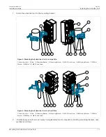
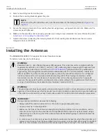
Page 16: ...le 6 Secure the mounting bracket to the wall with four 1 4 1 2 HEX screws four spring washers and four flat washers 7 Connect the arm bracket to the mounting bracket using a screw spring washer flat washer and nut Make sure the nut is hand tight 8 Connect the subscriber unit to the arm bracket using a screw spring washer flat washer and nut Make sure the nut is hand tight 9 Make sure the subscribe...

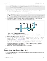
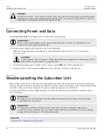
Page 17: ...Pole 3 Clamping Bracket 4 Mounting Bracket 5 M8 25 Hex Screw 6 M8 Spring Washer 7 M8 Flat Washer 8 M8 Nut 9 M8 70 Hex Screw 1 2 9 6 7 6 8 7 6 5 3 4 3 Figure 4 Mounting the Subscriber Unit to a Small Pole 1 Subscriber Unit 2 Pole 3 Clamping Bracket 4 Mounting Bracket 5 M8 25 Hex Screw 6 M8 Spring Washer 7 M8 Flat Washer 8 M8 Nut 9 M8 70 Hex Screw 2 Liberally apply an anti corrosion spray to all gal...

Page 18: ...all the subscriber unit when it is configured not to transmit and set it to operational mode remotely rather than having a technician enable transmission on site For maintenance of the subscriber unit or other operations which require RF exposure the exposure should be minimized in time and according to the regulations set forth by the country of installation or the Federal Communications Commissi...

Page 19: ...om any noise sources such as Switch Mode Power Supplies SMPS 1 1 4 3 3 5 2 6 Figure 5 Antenna and Lightning Protector Assembly 1 Drain Wire 2 RUGGEDCOM WIN5137 V 3 Shielded Coaxial Cable 4 Lightning Protector 5 Ground Wire 6 Antenna 4 Make sure the PWR LED on the subscriber unit is on 5 Adjust the position of the antenna until the maximum RSSI link quality reading is achieved A single RSSI LED ind...

Page 20: ...ace objects on or against them 2 Connect the power supply to the M12 4 pin male A coded PWR port on the subscriber unit 3 Connect a CAT 5e cable between the ETH port on the subscriber unit and a router switch Section 2 8 Weatherproofing the Subscriber Unit Most outdoor subscriber unit antenna and cable problems are caused by coaxial cable connections loosened by vibration allowing moisture to pene...

Page 21: ...on putty around the very end of the cable to form a seal between it and the base station 6 If the subscriber unit is installed in a marine environment e g wind farm substation coastal tower or marine vessel apply a coating of marine grease to all galvanized steel components including mounting brackets nuts washers and screws This is in addition to the anti corrosion spray applied during the mounti...

Page 22: ...lying self amalgamating tape make sure to stretch it to 2 3 of its original width to form a tight seal 1 Cut a strip of self amalgamating tape approximately 50 cm 19 7 in long 2 Apply one end of the tape to the cable end and tightly wrap it around the cable once fully making sure the tape overlaps 3 Tightly wrap the remainder of the tape down the cable making sure the tape overlaps with each pass ...

Page 23: ... Subscriber Unit Section 3 1 Configuring the Subscriber Unit Once the subscriber unit is installed and connected to the network it must be configured The RUGGEDCOM WIN5137 V features a Web based User Interface UI for all configuration management For more information about configuring the subscriber unit refer to the RUGGEDCOM WIN Subscriber Unit User Guide associated with the subscriber unit and t...

Page 24: ...Chapter 3 Device Management RUGGEDCOM WIN5137 V Installation Guide 18 Configuring the Subscriber Unit ...

Page 25: ...4 4 Operating Environment Section 4 5 Mechanical Specifications Section 4 6 Dimension Drawings Section 4 1 Power Supply Requirements The RUGGEDCOM WIN5137 V requires an external power supply that meets the following requirements Power Supply Type Class 2 Input Range 10 to 36 VDC Section 4 2 Power Consumption Typical Power Consumption 12 W Section 4 3 Radio and Modem Specifications Operating Freque...

Page 26: ... FFT Channels 1024 512FFT Type of Modulation QPSK 16 QAM 64 QAM Dynamic Range Receiver 20 to 100 dBm Dynamic Range Transmitter 20 to 27 dBm Section 4 4 Operating Environment The RUGGEDCOM WIN5137 V is rated to operate under the following environmental conditions Ambient Operating Temperature a 40 to 75 C 40 to 167 F Ambient Storage Temperature 40 to 75 C 40 to 167 F Ambient Relative Humidity b 5 t...

Page 27: ...er 4 Technical Specifications Dimension Drawings 21 Section 4 6 Dimension Drawings NOTE All dimensions are in millimeters unless otherwise stated 37 0 44 2 81 7 42 5 27 5 25 1 244 7 226 0 92 2 154 0 11 0 36 0 4 5 106 8 Figure 6 Overall Dimensions ...

Page 28: ...Chapter 4 Technical Specifications RUGGEDCOM WIN5137 V Installation Guide 22 Dimension Drawings ...

Page 29: ... WIN5137 V complies CONTENTS Section 5 1 1 CSA Section 5 1 2 European Union EU Section 5 1 3 TÜV Rheinland Section 5 1 4 ISED Section 5 1 5 FCC Section 5 1 6 IEEE Section 5 1 7 RoHS Section 5 1 1 CSA This subscriber unit meets the requirements of the following Canadian Standards Association CSA standards CAN CSA C22 2 No 60950 1 07 A1 2011 A2 2014 Information Technology Equipment Safety Part 1 Gen...

Page 30: ...roadband Data Transmission System Base Stations Ancillary Equipment and Services EN 50121 3 2 Railway Applications Electromagnetic Compatibility Rolling Stock Apparatus EN 50121 4 Railway Applications Electromagnetic Compatibility Emission and Immunity of the Signaling and Telecommunications Apparatus EN 50155 Railway applications Electronic Equipment Used on Rolling Stock Section 5 1 3 TÜV Rheinl...

Page 31: ...ned by turning the device off and on the user is encouraged to try to correct the interference by one or more of the following measures Reorient or relocate the receiving antenna Increase the separation between the device and receiver Connect the device into an outlet on a circuit different from that to which the receiver is connected Contact Siemens Customer Support for assistance IMPORTANT Chang...

Page 32: ...F 509 4 Salt Fog 5 NaCI 35 48h IEC 60068 2 14 Temperature Change 10 to 45 C 14 to 113 F 0 5 C min 0 9 F min for 2 cycles 40 to 30 C 40 to 22 F 1 C min 1 8 F min for 5 cycles Water Rain Intensity 0 01 m min 0 35 ft min 90 kPa 13 PSI for 30 minutes IEC 60068 2 18 IEC 529 IP65 IP67 Water Rain 0 01 m min 90 kPa 13 PSI for 15 minutes IEC 60068 2 6 Sine Vibration Velocity 5 mm s Displacement 1 5 mm Acce...

Page 33: ...e Tests 27 Test Description Test Levels Accelerator 180 m s 100 shocks in each direction IEC 60068 2 32 Nebs GR63 Free Fall Height 1 m 3 3 ft One fall on 3 faces 3 edges and 4 corners 30 C 86 F 90 to 100 for 2 cycles IEC 60068 2 30 Humidity Cycling 40 C 104 F 90 to 100 for 2 cycles ...

Page 34: ...Chapter 5 Certification RUGGEDCOM WIN5137 V Installation Guide 28 Environmental Type Tests ...

Reviews: