background image

RUGGEDCOM M969F

Installation Guide

Chapter 3

Device Management

Connecting to the Device

17

Device Management

This section describes how to connect to and manage the device.

CONTENTS

Section 3.1, “Connecting to the Device”

Section 3.2, “Configuring the Device”

Section 3.1

Connecting to the Device

The following describes the various methods for accessing the ROS console and Web interfaces on the device. For

more detailed instructions, refer to the 

ROS User Guide

 for the RUGGEDCOM M969F.

RS-232 Console Port

Connect a PC or terminal directly to the RS-232 console port to access the boot-time control and ROS interfaces.

The console port provides access to ROS's console and Web interfaces.

IMPORTANT!

The console port is intended to be used only as a temporary connection during initial configuration or

troubleshooting.

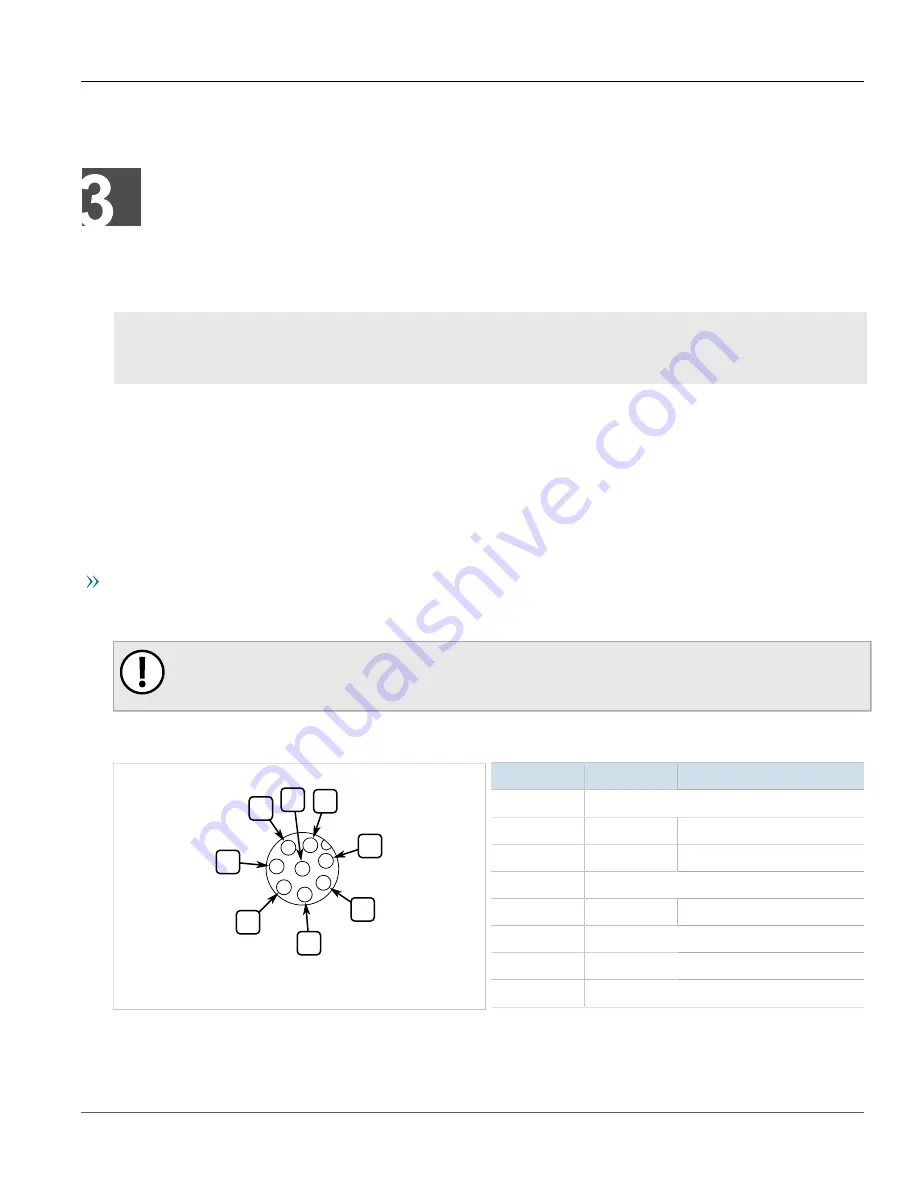
Connection to the console port is made using an M12-to-DB9 console cable. The following is the pin-out for the

console port:

2

4

1

3

5

7

6

8

Figure 13: M12 Console Port Pin Configuration

Pin

Name

Description

1

Reserved (Do Not Connect)

2

RX

Receive Data (from DTE)

3

TX

Transmit Data (from DTE)

4

Reserved (Do Not Connect)

5

GND

Common Ground

6

Reserved (Do Not Connect)

7

Reserved (Do Not Connect)

8

Reserved (Do Not Connect)

Summary of Contents for RUGGEDCOM M969F

Page 1: ...RUGGEDCOM M969F Installation Guide 07 2018 RC1349 EN 02 Preface Introduction 1 Installing the Device 2 Device Management 3 Communication Ports 4 Technical Specifications 5 Accessories 6 Certification 7 ...

Page 2: ...t and or networks They are important components in a holistic industrial security concept With this in mind Siemens products and solutions undergo continuous development Siemens recommends strongly that you regularly check for product updates For the secure operation of Siemens products and solutions it is necessary to take suitable preventive action e g cell protection concept and integrate each ...

Page 3: ...Siemens Address Siemens Canada Ltd Industry Sector 300 Applewood Crescent Concord Ontario Canada L4K 5C7 Telephone Toll free 1 888 264 0006 Tel 1 905 856 5288 Fax 1 905 856 1995 E mail ruggedcom info i ia siemens com Web https www siemens com ruggedcom ...

Page 4: ...RUGGEDCOM M969F Installation Guide iv ...

Page 5: ... Supported Fiber Optic Cables 6 1 5 Tamper Evident Security Seals 6 1 6 Ingress Protection 7 1 7 Decommissioning and Disposal 7 Chapter 2 Installing the Device 9 2 1 General Procedure 9 2 2 Unpacking the Device 10 2 3 Mounting the Device 10 2 4 Connecting the Failsafe Alarm Relay 11 2 5 Connecting Power 12 2 5 1 Power Supply Connector Pin Out 12 2 5 2 Power Supply Wiring 13 2 5 3 Disabling Line to...

Page 6: ...ber Optic Ethernet Port Specifications 24 5 5 Operating Environment 25 5 6 Mechanical Specifications 25 5 7 Dimension Drawings 26 Chapter 6 Accessories 29 6 1 Power 1 unit 29 6 2 Console 1 unit 30 6 3 Failsafe 1 unit 31 6 4 Ethernet 8 unit 32 6 5 LC Fiber Optic 2 unit 35 Chapter 7 Certification 39 7 1 Approvals 39 7 1 1 CSA 39 7 1 2 European Commission EC 40 7 1 3 FCC 40 7 1 4 FDA CDRH 40 7 1 5 IS...

Page 7: ...sing Documentation Training Customer Support Alerts The following types of alerts are used when necessary to highlight important information DANGER DANGER alerts describe imminently hazardous situations that if not avoided will result in death or serious injury WARNING WARNING alerts describe hazardous situations that if not avoided may result in serious injury and or equipment damage CAUTION CAUT...

Page 8: ...ique mix of IT Telecommunications expertise combined with domain knowledge in the utility transportation and industrial markets allows Siemens to provide training specific to the customer s application For more information about training services and course availability visit https www siemens com ruggedcom or contact a Siemens Sales representative Customer Support Customer support is available 24...

Page 9: ... Installation Guide Preface Customer Support ix Contact a local Siemens representative from Sales Technical Support Training etc Ask questions or share knowledge with fellow Siemens customers and the support community ...

Page 10: ...Preface RUGGEDCOM M969F Installation Guide x Customer Support ...

Page 11: ...tion The embedded RUGGEDCOM Rugged Operating System ROS provides advanced layer 2 and layer 3 networking functions advanced cyber security features and a full array of intelligent functionality for high network availability and manageability Coupled with the ruggedized hardware design the RUGGEDCOM M969F is ideal for creating mission critical real time control applications in any harsh environment...

Page 12: ...r supply Universal high voltage range 88 300 VDC or 85 264 VAC Popular low voltage DC ranges 12 24 48 VDC Dual redundant parallel load sharing power supplies option Can be powered from different sources for ultimate redundancy Available with M23 style connectors CSA UL 60950 1 safety approved to 85 C 185 F Simple Plug and Play Operation Automatic learning of up to 8192 MAC addresses Auto negotiati...

Page 13: ...10 9 11 Figure 1 RUGGEDCOM M969F M12 Connectors Shown 1 Copper Ethernet Ports 2 Port Status LED 3 POWER 1 LED 4 POWER 2 LED 5 ALARM LED 6 RS 232 Console Port 7 Failsafe Output Relay 8 M12 Power Supply Port 9 Fiber Optic Ethernet Ports 10 Surge Ground Connection 11 Chassis Ground Connection ...

Page 14: ...M M969F RJ45 Connectors Shown 1 Copper Ethernet Ports 2 Port Status LED 3 POWER 1 LED 4 POWER 2 LED 5 ALARM LED 6 RS 232 Console Port 7 Failsafe Output Relay 8 M23 Power Supply Port 9 Fiber Optic Ethernet Ports 10 Surge Ground Connection 11 Chassis Ground Connection Port Status LED Indicate the status of each port ...

Page 15: ...ng to the Device Copper Fiber Ethernet Ports For information about available copper and fiber Ethernet ports refer to Chapter 4 Communication Ports Section 1 3 Required Tools and Materials The following tools and materials are required to install the RUGGEDCOM M969F Tools Materials Purpose AC or DC power cord 16 AWG For connecting power to the device CAT 5 Ethernet cables For connecting the device...

Page 16: ...a Laser optimized Section 1 5 Tamper Evident Security Seals In compliance with the security requirements of the Federal Information Processing Standards FIPS140 2 FIPS compliant tamper evident security seals are applied to potential access points on this device Security seals provide evidence of unauthorized tampering or removal of components IMPORTANT Worn damaged or missing seals must be replace...

Page 17: ...nused ports on the IP67 Industrial Ethernet Switch It has an IP67 rated seal that keeps out all contaminants like dirt oil and water Figure 3 Caps Section 1 7 Decommissioning and Disposal Proper decomissioning and disposal of this device is important to prevent malicious users from obtaining proprietary information and to protect the environment Decommissioning This device may include sensitive pr...

Page 18: ...Chapter 1 Introduction RUGGEDCOM M969F Installation Guide 8 Decommissioning and Disposal ...

Page 19: ...e IMPORTANT This product contains no user serviceable parts Attempted service by unauthorized personnel shall render all warranties null and void Changes or modifications not expressly approved by Siemens Canada Ltd could invalidate specifications test results and agency approvals and void the user s authority to operate the equipment IMPORTANT This product should be installed in a restricted acce...

Page 20: ...r damaged contact Siemens for assistance Section 2 3 Mounting the Device The RUGGEDCOM M969F is designed to be mounted on a panel by affixing the top and bottom flanges of the device to a panel using screws IMPORTANT Heat generated by the device is channeled outwards from the enclosure As such it is recommended that 2 5 cm 1 in of space be maintained on all open sides of the device to allow for so...

Page 21: ... Connecting the Failsafe Alarm Relay The Failsafe output relay is provided to signal critical error conditions that may occur on the RUGGEDCOM M969F series switches The contacts are energized upon power up of the unit and remain energized until a critical error occurs One common application for this output is to signal an alarm if a power failure or removal of control power occurs The proper relay...

Page 22: ...r The RUGGEDCOM M969F supports dual redundant power supplies Power Supply 1 PS1 and Power Supply 2 PS2 CONTENTS Section 2 5 1 Power Supply Connector Pin Out Section 2 5 2 Power Supply Wiring Section 2 5 3 Disabling Line to Ground Transient Protection Section 2 5 1 Power Supply Connector Pin Out The following is the pin out for the M23 A coded power supply connector 5 4 3 2 1 Figure 6 M23 Power Sup...

Page 23: ...al if the power source is AC 5 PS2 Live PS2 Live is connected to the positive terminal if the power source is DC or to the Live terminal if the power source is AC Section 2 5 2 Power Supply Wiring The following illustrates how to connect the RUGGEDCOM M969F to a single or dual power supplies NOTE For 100 240 VAC rated equipment a 250 VAC appropriately rated circuit breaker must be installed For 88...

Page 24: ...r Supply Wiring Example M23 Connector 1 M23 Power Connector 2 Ground Bus 3 300 VDC Breaker 4 DC Power Source Dual AC DC Power Supply Wiring 1 2 6 4 5 8 4 5 3 2 1 7 4 5 3 3 Figure 9 AC and AC Power Supply Wiring Example 1 M23 Power Connector 2 Ground Bus 3 Line 4 250 VAC Breaker 5 Neutral 6 110 230 VAC Power Source PS2 7 110 230 VAC Power Source PS1 8 Safety ...

Page 25: ...er 9 DC Power Source PS1 3 2 1 4 5 1 2 3 5 3 4 Figure 11 DC and DC Power Supply Wiring Example 1 M23 Power Connector 2 Ground Bus 3 300 VDC Breaker 4 DC Power Source PS2 5 DC Power Source PS1 Section 2 5 3 Disabling Line to Ground Transient Protection All line to ground transient energy is shunted to the Surge Ground terminal In cases where users require the inputs to be isolated from ground remov...

Page 26: ...Chapter 2 Installing the Device RUGGEDCOM M969F Installation Guide 16 Disabling Line to Ground Transient Protection Figure 12 Surge Ground Chassis Ground Connection ...

Page 27: ... PC or terminal directly to the RS 232 console port to access the boot time control and ROS interfaces The console port provides access to ROS s console and Web interfaces IMPORTANT The console port is intended to be used only as a temporary connection during initial configuration or troubleshooting Connection to the console port is made using an M12 to DB9 console cable The following is the pin o...

Page 28: ...actory default IP address for the RUGGEDCOM M969F is https 192 168 0 1 For more information about available ports refer to Chapter 4 Communication Ports Section 3 2 Configuring the Device Once the device is installed and connected to the network it must be configured All configuration management is done via the RUGGEDCOM ROS interface For more information about configuring the device refer to the ...

Page 29: ... determine which ports are equipped on the device refer to the factory data file available through ROS For more information on how to access the factory data file refer to the ROS User Guide for the RUGGEDCOM M969F Each communication port type has a specific place in the RUGGEDCOM M969F chassis 2 1 Figure 14 Port Assignment M12 Connectors Shown 1 M12 D Coded Copper Ethernet Ports 2 Fiber Optic Eth...

Page 30: ...OM M969F supports eight 10 100Base TX Ethernet ports that allow connection to standard Category 5 CAT 5 unshielded twisted pair UTP cables with RJ45 male connectors or M12 male connectors The RJ45 M12 connectors are directly connected to chassis ground on the device and can accept CAT 5 shielded twisted pair STP cables WARNING Electric shock hazard risk of serious personal injury and or equipment ...

Page 31: ... Data 4 Reserved Do Not Connect 5 Reserved Do Not Connect 6 TX Transmit Data 7 Reserved Do Not Connect 8 Reserved Do Not Connect Pin Out M12 The following is the pin out description for the M12 connectors Figure 17 4 Pin D Coded M12 Ethernet Port Pin Configuration Pin 10 100Base Tx Signal 1 TX 2 RX 3 TX 4 RX Specifications For specifications on the available copper Ethernet ports refer to Section ...

Page 32: ...DCOM M969F Installation Guide 22 Fiber Optic Ethernet Ports 2 1 Figure 18 LC Port 1 Tx Connector 2 Rx Connector For specifications on the available fiber optic Ethernet ports refer to Section 5 4 Fiber Optic Ethernet Port Specifications ...

Page 33: ...on 5 6 Mechanical Specifications Section 5 7 Dimension Drawings Section 5 1 Power Supply Specifications Power Supply Type Minimum Input Maximum Input Internal Fuse Rating Isolation Maximum Power Consumption 12 24 VDC 10 VDC 36 VDC 24 VDC 18 VDC 36 VDC 48 VDC 36 VDC 72 VDC 1 5 kVDC HI 125 250 VDC b 88 VDC 300 VDC 4 kVAC HI 110 230 VAC b 85 VAC 265 VAC 3 15A T a 5 5 kVDC 10 W a T denotes time delay ...

Page 34: ...et Optical Specifications Tx dBm Mode Connector Cable Type µm Tx λ nm c Min Max Rx Sensitivity dBm Rx Saturation dBm Typical Distance km Power Budget dB SM LC 9 125 1300 15 8 32 3 20 17 SM LC 9 125 1300 5 0 35 3 50 30 SM LC 9 125 1300 0 5 37 0 90 37 MM LC 50 125 850 22 5 14 31 14 2 8 5 c Typical Gigabit Ethernet Optical Specifications NOTE All cabling is duplex type unless otherwise specified Maxi...

Page 35: ... is rated to operate under the following environmental conditions Ambient Operating Temperature e 40 to 85 C 40 to 185 F f Ambient Storage Temperature 40 to 85 C 40 to 185 F Ambient Relative Humidity g 5 to 95 Maximum Altitude h e Measured from a 30 cm 12 in radius surrounding the center of the RUGGEDCOM M969F enclosure f Reduced to 40 to 80 C 40 to 76 F when equipped with a 100Base FX single mode...

Page 36: ...ical Specifications RUGGEDCOM M969F Installation Guide 26 Dimension Drawings Section 5 7 Dimension Drawings NOTE All dimensions are in inches unless otherwise stated Figure 19 8 RJ45 IP67 Ethernet Ports and M23 Power ...

Page 37: ...RUGGEDCOM M969F Installation Guide Chapter 5 Technical Specifications Dimension Drawings 27 Figure 20 8 M12 D Code Ethernet Ports and M23 Power ...

Page 38: ...Chapter 5 Technical Specifications RUGGEDCOM M969F Installation Guide 28 Dimension Drawings ...

Page 39: ...TENTS Section 6 1 Power 1 unit Section 6 2 Console 1 unit Section 6 3 Failsafe 1 unit Section 6 4 Ethernet 8 unit Section 6 5 LC Fiber Optic 2 unit Section 6 1 Power 1 unit M23 Power Mating Connector Figure 21 M23 Power Mating Connector Description M23 5pin female connector 600V IP68 rated Order Code 99 60 0007 Cable Specifications 3 18 AWG jacket OD range 0 20 0 48 ...

Page 40: ...jacket for dual power supply Order Code 99 43 0129 001 Cable Specifications Overmold R A M23 plug to free end 5 m Section 6 2 Console 1 unit M12 Console Port Mating Cable Figure 23 M12 Console Port Mating Cable Description M12 8pin A code male to DB9 female unshielded PUR jacket cable 30V 4A 3m Order Code 99 43 0023 001 Cable Specifications M12 8pin A code male to free end 3m ...

Page 41: ...r Figure 24 M12 Console Port Mating Connector Description M12 straight plug 8 pole A coded IP67 rated Order Code 99 60 0002 Section 6 3 Failsafe 1 unit M12 FailSafe Port Mating Cable Figure 25 M12 FailSafe Port Mating Cable Description M12 4pole A coded unshielded PUR Jacket cable 3m Order Code 99 43 0024 001 ...

Page 42: ...t Mating Connector Description M12 straight plug 4 pole A coded IP67 rated Order Code 99 60 0009 Section 6 4 Ethernet 8 unit M12 D code Ethernet Port Mating Cable Figure 27 M12 D code Ethernet Port Mating Cable Description M12 D code to RJ45 patch cable 3meters Order Code 99 43 0040 001 Cable Specifications M12 D code male 4 pin CAT5e 3m ...

Page 43: ...net Port Mating Connector Description M12 straight plug 4 pole D coded IP67 rated Order Code 99 60 0008 M12 D Code Ethernet Port Mating Cable Figure 29 M12 D Code Ethernet Port Mating Cable Description M12 male D code to male D code shielded PUR jacket patch cable 5 meters Order Code 99 43 0041 001 Cable Specifications M12 male 4 pin CAT 5e 5m ...

Page 44: ...gure 30 IP67 Metal RJ45 Ethernet Port Mating Cable Description IP67 Metal RJ45 plug to RJ45 CAT5e shielded patch cable 3m Order Code 99 43 0182 001 IP67 Metal RJ45 Ethernet Port Mating Connector Figure 31 IP67 Metal RJ45 Ethernet Port Mating Connector Description IP67 Metal RJ45 plug field attachable Order Code 99 60 0010 ...

Page 45: ...RJ45 Ethernet Port Mating Cable Description IP67 Metal RJ45 plug on both ends Category 5e shielded patch cable 3m Order Code 99 43 0039 001 Section 6 5 LC Fiber Optic 2 unit LC Port Mating Connector Figure 33 LC Port Mating Connector Description Cable Multimode Metal IP67LC to LC Multimode fiber cable 3meters IP67 rated Order Code 99 43 0057 001 ...

Page 46: ...meters IP67 rated Order Code 99 43 0055 001 LC Port Mating Connector Figure 35 LC Port Mating Connector Description Cable Multimode Metal IP67 LC to Metal IP67 LC Multimode fiber cable 3meters IP67 rated Order Code 99 43 0047 001 Figure 36 LC Port Mating Connector Description Cable Singlemode Metal IP67 LC to Metal IP67 LC Singlemode fiber cable 3 meters IP67 rated Order Code 99 43 0053 001 ...

Page 47: ...RUGGEDCOM M969F Installation Guide Chapter 6 Accessories LC Fiber Optic 2 unit 37 LC RJ45 Port Cap Figure 37 LC RJ45 Port Cap Description RJ45 outlet cap IP67 Metal Order Code 99 60 0011 ...

Page 48: ...Chapter 6 Accessories RUGGEDCOM M969F Installation Guide 38 LC Fiber Optic 2 unit ...

Page 49: ...his section details the standards to which the RUGGEDCOM M969F complies CONTENTS Section 7 1 1 CSA Section 7 1 2 European Commission EC Section 7 1 3 FCC Section 7 1 4 FDA CDRH Section 7 1 5 ISED Section 7 1 6 RoHS Section 7 1 7 Other Approvals Section 7 1 1 CSA This device meets the requirements of the following Canadian Standards Association CSA standards under certificate 16 70065161 CAN CSA C2...

Page 50: ... used throughout the European community A copy of the CE Declaration of Conformity is available from Siemens Canada Ltd For contact information refer to Contacting Siemens Section 7 1 3 FCC This device has been tested and found to comply with the limits for a Class A digital device pursuant to Part 15 of the FCC Rules These limits are designed to provide reasonable protection against harmful inter...

Page 51: ...tronic Information Products A copy of the Material Declaration is available online at https support industry siemens com cs ww en view 109738831 Section 7 1 7 Other Approvals This device meets the requirements of the following additional standards IEEE 1613 IEEE Standard Environmental and Testing Requirements for Communications Networking Devices in Electric Power Substations IEC 61000 6 2 Electro...

Page 52: ... Procedure II Operational High Temperature Method 501 4 Procedure I Storage High Temperature Method 501 4 Procedure II Operational Low Temperature Method 502 4 Procedure I Storage Low Temperature Method 502 4 Procedure II Operational Temperature Shock Method 503 4 Procedure I Storage Acceleration Method 513 5 Procedure II Salt Fog Method 509 4 Procedure I MIL STD 810F Vibration Method 514 5 MIL ST...

Page 53: ...rts 10 V 3 IEC 61000 4 8 Magnetic Field Enclosure ports 40 A m continuous 1000 A m for 1 s DC Power ports 30 for 0 1 s 60 for 0 1 s 100 for 0 05 s IEC 61000 4 29 30 for 1 period 60 for 50 periods IEC 61000 4 11 Voltage Dips Interrupts AC Power ports 100 for 5 periods 100 for 50 periods 2 Signal ports 2 5 kV common 1 kV differential mode 1MHz 3 DC Power ports 2 5 kV common 1 kV differential mode 1M...

Page 54: ...kV common differential mode 1MHz Oscillatory AC Power ports 2 5 kV common differential mode 1MHz Signal ports 5 kV Failsafe Relay DC Power ports 5 kV HV Impulse AC Power ports 5 kV Signal ports 2 kV DC Power ports 1 5 kV Dielectric Strength AC Power ports 2 kV Environmental Type Tests NOTE Class 2 refers to Measuring relays and protection equipment for which a very high security margin is required...

Page 55: ...e Tests 45 Test Description Test Levels Severity Levels IEC 60529 IPx6 Ingress Protection Water Jet 100 l m 2 5 m as per 14 2 6 IEC 60529 IPx7 Ingress Protection Water Submersion 30 min 1 m as per 14 2 7 IEC 60529 IP6x Ingress Protection Dust Talcum 2 kg m 3 for 8 h as per 13 4 Cat 1 2 ...

Page 56: ...Chapter 7 Certification RUGGEDCOM M969F Installation Guide 46 EMC and Environmental Type Tests ...

Reviews: