background image

4/11 

Siemens 

Temperature Controller RRV851 


CE1N2725en 

Building Technologies 


27.08.2007 

  Remote room temperature sensing: The QAX850 can be used as a master control 

unit without using the built-in temperature sensor. A separate room sensor (QAA32) 
can be mounted in a location more convenient for accurate temperature acquisition 

  Return air temperature sensing: A temperature sensor (QAH11.1) can be mounted in 

the return air path of the FCU if accurate temperature acquisition in the room is not 
possible 

  2-pipe application heating/cooling changeover: For application A8 (2-pipe FCU) a 

temperature sensor (QAH11.1/ARG86.3) is clamped to the water pipe in order to 
activate heating/cooling mode changeover  

 
The RRV851 controller can be configured for a 1- or 3-speed fan. Voltage-free (SPST) 
relay outputs Q74, Q84 and Q94 can switch loads up to AC 250 V, 6 (4) A. Power is 
supplied via terminal Q71. The low-speed terminal is used when a 1-speed fan is 
configured. On fan startup, high-speed will be activated first for approximately 
3 seconds and then resume the selected speed. In Auto Fan mode, the fan speeds will 
be activated automatically depending on demand.  
For further details on auto fan speed control, refer to the Application Manual. 
 

  Output Y1: Cooling or compressor output  

  Output Y2: Heating or reversing valve output  

  Output Y3: Auxiliary output that can be configured for auxiliary heating, emergency 

heating, 2

nd

 step cooling or dual compressor  

Output control is 2-position. 3-position modulating can be selected via parameter P17 
for applications A1, A2 and A8 only. 

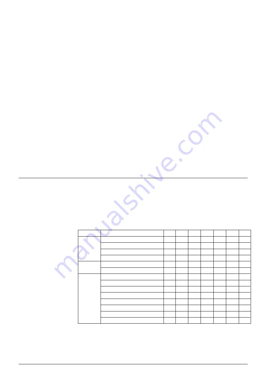
Configuration 

Initial application setup of the RRV851 controller to match the connected HVAC 
equipment is made by the selection of DIP switch positions. DIP switches are located 
on the top of the controller. An adhesive label is included in the RRV851 packaging box 
for the final recording of the DIP switch positions. This can be placed on the DIP switch 
block to avoid unauthorized changes. Further parameter settings can be made via the 
QAX850 if required.  


Function 

Selections 

1 2 3 4 5 6 7 

Auxiliary heating 20 min delay 

off off 

- - - - - 

Auxiliary 

heating 

10 

min 

delay 

on 

off 

- - - - - 

Emergency 

heating 

via 

D2  off 

on 

- - - - - 

Y3  
Auxiliary 
output  

2

nd


stage 

cool 

or 

compressor 

on 

on 

- - - - - 

Single 

speed 

- - off 

- - - - 

Fan 
speed 

Three speed 

on 

- - - - 

A1

 – Heating only 

- -  - 

off off off off 

A2

 – Cooling only 

-  -  -  on off off off 

A3

 – Cool./(heat. 3 speed fan)  -  -  -  off on off off 

A4

 – Cool./(heat. 1 speed fan)  -  -  -  on on off off 

A5

 – Heat pump (comp + RV)  -  -  -  off off on off 

A6

 – Heat pump (heat/cool) 

-  -  -  on off on off 

A7

 – 4-pipe FCU 

-  -  -  off on on off 

Applica-
tion 

A8

 – 2-pipe FCU 

-  -  -  on on on off 


Default (as delivered) positions are in bold text. 
 

Fan speed outputs 

Heat/cool outputs 

DIP switches 

DIP switch settings 

Summary of Contents for RRV851

Page 1: ...al applications The RRV851 controller is designed for central ducted HVAC systems that require easy operation by the building occupant The MMI to be connected to the controller is the QAX850 master room unit Fan heating and or cooling outputs control the temperature in the building The RRV851 controller can be configured for various types of HVAC equipment These include Heating only ducted systems...

Page 2: ...summary Type reference Description Compatible with RRV851 Temperature controller QAX850 Master room unit QAA32 Room temperature sensor QAH11 1 Cable temperature sensor The QAX850 is the master MMI for the RRV851 and must be ordered as a separate item Any additional remote temperature sensors must also be ordered separately Terminal covers are included in the RRV851 box Not suitable for use with th...

Page 3: ...only Two digital inputs are provided A potential free contact closed across the D1 and D_GND terminals will override to Comfort mode only when the mode selector is set to Auto Timer mode D2 can be configured for an emergency heating enable signal or an external fault lockout signal Either of these functions can be selected via the configuration DIP switches When emergency heating is selected a pot...

Page 4: ...put Y1 Cooling or compressor output Output Y2 Heating or reversing valve output Output Y3 Auxiliary output that can be configured for auxiliary heating emergency heating 2nd step cooling or dual compressor Output control is 2 position 3 position modulating can be selected via parameter P17 for applications A1 A2 and A8 only Configuration Initial application setup of the RRV851 controller to match ...

Page 5: ...have been made and power is connected Default parameter settings are based on the application selected and may be modified if required Refer to the list below Parameters cannot be accessed if the system is in Off mode Refer to the Installation Instructions for setup details and the Application Manual for default parameter values No Parameter Range P00 Temperature scale C F P01 Frost protection lim...

Page 6: ... operation Easy access is required for service personnel Local installation regulations must be observed The Mounting Instructions are included in the RRV851 controller packaging When not mounting within a panel cable strain reliefs must be used for all wiring to AC 230 V terminals The conductors must be secured with cable ties see diagram Cable strain reliefs should be used for all wiring to avoi...

Page 7: ...xternal supply line fusing Non renewable fuse slow Automatic line cutout Release characteristic max 10 A max 13 A B C D to EN 60 898 Relay contacts Y1x Y2x Y3x Relay output Switching voltage AC current At 250 V At 19 V Switch on current Contact life potential free max AC 250 V min AC 19 V max 3 A res 1 A ind cos φ 0 6 min 5 mA min 20 mA max 5 A 1 s 1 105 cycles Boiler Q1x Relay contacts Q7x Relay ...

Page 8: ...midity Mechanical conditions IEC 721 3 3 class 3K5 0 50 C 5 95 r h non condensing class 3M2 Transport to Climate conditions Temperature Humidity Mechanical condition IEC 721 3 2 class 2K3 25 70 C 95 r h class 2M2 Classification to EN 60 730 Mode of operation automatic controls type 1B Degree of contamination controls Environment 2 Rated surge voltage 4000 V Software class A Materials and colors Co...

Page 9: ...4 Q71 1 2 3 F1 1 Y11 Y12 Y14 Y21 Y22 Y24 Y34 Y31 Y1 N1 N2 AC 230V L N TX TX 485 gnd RS485 Y2 B1 F2 Y3 B1 External temperature sensor optional or pipe changeover sensor application A8 CR1 Compressor relay stage 1 CR2 Compressor relay stage 2 D1 Remote activation of Comfort mode D2 Fault or emergency heating F1 3 speed fan F1 External supply line fusing max 10 A F2 1 speed fan N1 RRV851 controller N...

Page 10: ... fusing must be used All input and bus terminals are not protected against connection to AC 230 V Observe the technical data for fan relay outputs Max AC 250 V 6 4 A All output cables used must satisfy insulation requirements with regard to mains potential AC 24 V outputs must be segregated from AC 250 V outputs Care should be taken when cables pass through sharp metal openings conduits or ducts D...

Page 11: ...iemens Temperature Controller RRV851 CE1N2725en Building Technologies 27 08 2007 Dimensions Without terminal covers With terminal covers Dimensions in mm 2005 2007 Siemens Switzerland Ltd Subject to alteration ...

Reviews: