


Installation, Maintenance & Troubleshooting guide
| Version 02
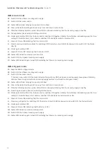
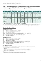
If fault still exists, then
4
5G : - Check the rated operational voltage of the starter in incoming terminal block (TB1) between L1-L2, L2-L3, L1-L3 with
suitable equipment e.g. multimeter.
- Check whether the 3-phase voltage in the incoming terminals of terminal block TB1 is >Maximum voltage allowed.
(Refer table no.13).
4
5H : - Keep the 3-phase voltage to the incoming terminals of terminal block TB1 to a voltage between min.required voltage
& Max.voltage allowed (Refer table no.13).
- Repeat the steps from 5A to 5E and then go to step no.5I
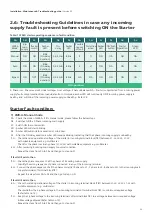
If fault still exists, then
5
5G : - Check the rated operational voltage of the starter in incoming terminal block (TB1) between L1-L2, L2-L3, L1-L3.
- Check whether the operational line voltage difference between any 2 phase in the incoming. terminals of terminal block
TB1 is >50V.
5
5H : - Starter will be operational only if the incoming supply voltage difference between any 2 phase in the incoming terminal
block TB1 of the starter is <=50V.
- Repeat the steps from 5A to 5E and then go to step no.5I
5I : Amber LED will remain ON continously indicating that the fault is cleared
5J : Press the Green ON push button to switch ON the starter.
5K : Motor gets switched ON. Star & Line contactor switches ON together initially, then after 6sec (depending upon the time
setting of star delta timer), star contactor switches OFF and Delta contactor switches ON.
5L : Green LED turns ON indicating that the motor is ON.
21
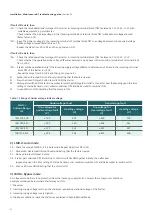
2) LMR-A: Auto mode
5A : Check the mode of LMR-A, if it is Auto mode. Repeat steps from 5B to 5H.
5I : Amber LED will remain ON continously indicating that the fault is cleared
5J : No need to press ON push button
5K : Starter gets switched ON. Star & Line contactor switches ON together initially, then after 6sec
(depending upon the time setting of star delta timer), star contactor switches OFF and Delta contactor switches ON.
5L : Green LED turns ON indicating that the motor is ON.
3) LMR-A: Bypass mode
As in Bypass mode there is no protection from the incoming supply faults, however there may some conditions,
example mentioned below where Starter may not ON –
1. Phase loss
2. Incmoing supply voltage less than the minimum required operational voltage of the Starter.
3. Incoming supply voltage is very high etc.......
In the above conditions check the Starters as explained in Auto & Manual Mode.
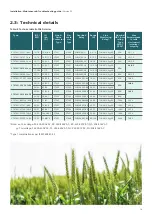
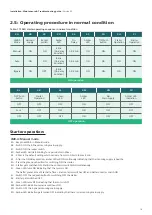
≤ 195
≤ 250
205
260
≥ 400
≥ 455
390
445
(Z6) 200-400
(Z8) 260-460
Table: 13 Range of Under voltage & Over voltage
≤ 313
≤ 294
323
304
≥ 457
≥ 418
447
408
(R0) 323-457
(Q0) 304-418
Starter
Voltage Range
(V)
Undervoltage fault
Trip voltage for
undervoltage fault
(V)
Healthy voltage
(V)
Trip voltage for
Overvoltage fault
(V)
Healthy voltage
(V)
Overvoltage fault
Summary of Contents for RAJA+
Page 1: ...Installation Maintenance Troubleshooting Guide For RAJA Agriculture Starters Controllers ...
Page 5: ...2 2 Wiring Diagram FASD 1 Installation Maintenance Troubleshooting guide Version 02 5 ...
Page 6: ...Control logic diagram 6 Installation Maintenance Troubleshooting guide Version 02 ...
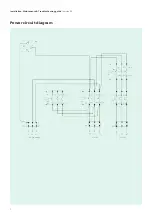
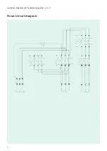
Page 7: ...Power circuit diagram 7 Installation Maintenance Troubleshooting guide Version 02 ...
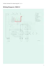
Page 8: ...8 Wiring Diagram FASD 2 Installation Maintenance Troubleshooting guide Version 02 ...
Page 9: ...9 Control logic diagram Installation Maintenance Troubleshooting guide Version 02 ...
Page 10: ...10 Power circuit diagram Installation Maintenance Troubleshooting guide Version 02 ...
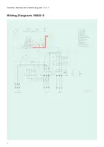
Page 11: ...Wiring Diagram FASD 3 Installation Maintenance Troubleshooting guide Version 02 11 ...
Page 12: ...Control logic diagram 12 Installation Maintenance Troubleshooting guide Version 02 ...
Page 13: ...Power circuit diagram 13 Installation Maintenance Troubleshooting guide Version 02 ...