


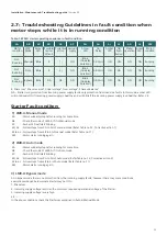


#: Phase loss
1
, Phase reversal
2
, Under voltage
3
, Over voltage
4
, Phase unbalance
5
NA – Starter is unprotected from incoming power
supply faults,only protection from load side faults. In this mode, amber LED will continously ON if incoming power supply is
healthy and will blink if the incoming power supply is unhealthy – Refer 2.8
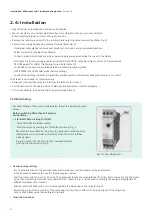
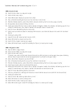
1) LMR-A: Manual mode
5A : Check the mode of LMR-A, if it is manual mode, please follow the below steps.
5B : Switches ON the 3-Phase incoming main supply.
5C : Switch ON the rocker switch
5D : Amber LED will start blinking
5E : Amber LED will blink for a duration of min.30sec.
5F : After the ON delay duration, amber LED remains blinking indicating that the 3phase incoming supply is unhealthy.
1
5G : - Check the rated operational voltage of the starter in incoming terminal block (TB1)between L1- L2 L2-L3, L1-L3
with suitable equipment e.g. multimeter.
- Check for the phase loss in any phase (L1,L2,L3) with suitable equipment e.g. multimeter.
1
5H: - After resuming incoming main supply to normal condition,
- Repeat the steps from 5A to 5E and then go to step no.5I
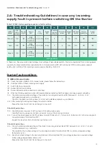
If fault still exists, then
2
5G : - Check the phase sequence of all the phases of incoming main supply.
- Identify the wrong sequence of phase connected in any of the incoming terminal.
2
5H: - Connect the phase sequence of all the phases correctly (R phase to L1 , Y phase to L2, B phase to L3) to the incoming main
supply terminals of Terminal block TB1.
- Repeat the steps from 5A to 5E and then go to step no.5I
If fault still exists, then
3
5G : - Check the rated operational voltage of the starter in incoming terminal block (TB1) between L1-L2, L2-L3, L1-L3 with
suitable equipment e.g. multimeter.
- Check whether the 3-phase voltage in the incoming terminals of terminal block TB1 is <minimum required voltage
(Refer table no.13).
3
5H : - Keep the 3-phase voltage to the incoming terminals of terminal block TB1 to a voltage between min.required voltage
& Max.voltage allowed (Refer table no.13).
- Repeat the steps from 5A to 5E and then go to step no.5I
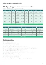
2.6: Troubleshooting Guidelines in case any incoming
supply fault is present before switching ON the Starter
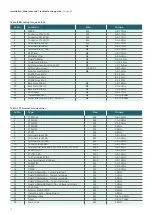
Starter Fault conditon:
LMR-A
Mode
Manual
Auto
Bypass
3
ф
main
supply
ON
ON
ON
Rocker
switch
ON
ON
ON*
On-
Delay
0.5-5min
0.5-5min
0.5-5min
Amber
LED
Blink
(On-delay
duration)
Blink
(On-delay
duration)
Blink
(On-delay
duration)
Amber
LED
Blink
Blink
Blink
#
#
NA
Possible
causes
of fault
1)
2)
NA
ON
ON
ON
ON
ON
Corrective
action
Amber
LED
‘ON’ Push
button
Starter
Operation
ON
ON
NA
ON
ON
ON
ON
Green
LED
Table: 12 FASD starter operating sequence in fault condition
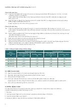
5A
5B
5C
5D
5E
5F
5G
5H
5L
5J
5K
5I
Installation, Maintenance & Troubleshooting guide
| Version 02
20
ON operation
Summary of Contents for RAJA+
Page 1: ...Installation Maintenance Troubleshooting Guide For RAJA Agriculture Starters Controllers ...
Page 5: ...2 2 Wiring Diagram FASD 1 Installation Maintenance Troubleshooting guide Version 02 5 ...
Page 6: ...Control logic diagram 6 Installation Maintenance Troubleshooting guide Version 02 ...
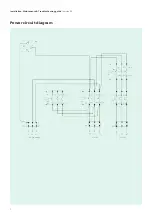
Page 7: ...Power circuit diagram 7 Installation Maintenance Troubleshooting guide Version 02 ...
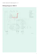
Page 8: ...8 Wiring Diagram FASD 2 Installation Maintenance Troubleshooting guide Version 02 ...
Page 9: ...9 Control logic diagram Installation Maintenance Troubleshooting guide Version 02 ...
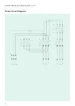
Page 10: ...10 Power circuit diagram Installation Maintenance Troubleshooting guide Version 02 ...
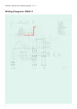
Page 11: ...Wiring Diagram FASD 3 Installation Maintenance Troubleshooting guide Version 02 11 ...
Page 12: ...Control logic diagram 12 Installation Maintenance Troubleshooting guide Version 02 ...
Page 13: ...Power circuit diagram 13 Installation Maintenance Troubleshooting guide Version 02 ...