


17
PAD-4 Installation, Operation and Maintenance Manual
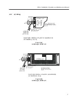
2.8
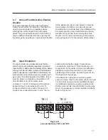
Input Emulation
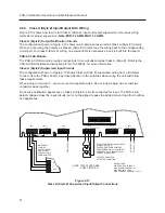
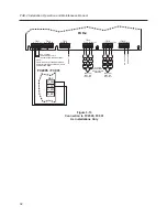
The input circuits are normally driven by the fire
alarm control unit notification appliance circuit and
thus the PAD-4 will monitor the polarity of the voltage
coming from the fire alarm control unit to determine
when to operate the output NACs. Alternatively, the
input circuits can be driven simply by a switch, such
as a relay. If a switch operates the NACs, then it
must be wired in a metallic conduit within 20 ft
from the PAD-4 and in the same room.
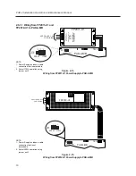
Jumpers J11 and J12 configure which mode is
active for input 1 and jumpers J13 and J14
configure which mode is active for input 2. If
jumpers are connected to pins 1 and 2, then a
switch will activate the inputs. If jumpers are
connected to pins 2 and 3, then inputs are nor-
mally driven by fire alarm control unit notification
appliance circuits. See Section 5-2 for correct
positioning of this jumper, and see Figure 2-5 for
the location of this jumper.
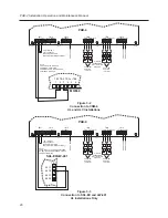
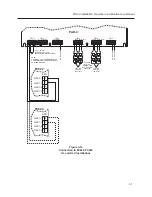
If the PAD-4 is configured to monitor a switch,
such as a relay, then the fire alarm control unit will
not be able to receive trouble conditions through
its notification appliance circuit connected to the
PAD-4 input circuits. Use the PAD-4 trouble relay
when it is necessary to monitor trouble conditions.
Refer to Figure 3-8.
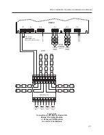
TB11
TB12
1+
1-
1
2+
2-
2
1
1
COM NC
INPUT 1
INPUT 2
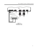
Figure 2-17
Connect Switches TB11 and TB12
2. 7
Ground Fault Detection Enable/
Disable
For some applications (when used with RSA-
Series annunciators, for instance), the PAD-4 is
used to provide power to an auxiliary device
which gets a control signal from a fire alarm
panel. The ground fault reference for the PAD-4
may be different than the reference used by the
fire alarm panel, resulting in a ground fault trouble
at the panel even when none exists. To remedy
this condition, the PAD-4 can have its ground
fault detection circuit disabled. Once disabled, the
fire alarm panel’s ground fault detection circuitry
will detect any ground fault in the system. See
Section 5-2 for correct positioning of this jumper,
and see Figure 2-5 for the location of this jumper.