


13
PAD-4 Installation, Operation and Maintenance Manual
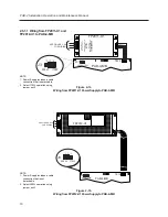
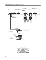
2.6.3
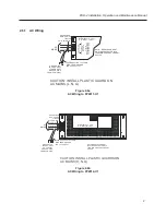
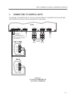
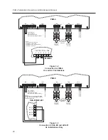
Class B (Style Y) Input/Output NAC Wiring
Figure 2-12 shows how to wire for Class B (Style Y) input and output supervision. Use in/out wiring
methods for proper supervision.
Class B (Style Y) Output Notification Circuits
Figure 2-12 shows four, 1.5 amp devices wired as Class B (Style Y) circuits.
Place a 24K ohm EOL resistor (provided) at the end of each loop to enable notification output supervi-
sion when using all outputs as Class B (Style Y) notification circuits. The 24K EOLs must be wired to the
terminals whether or not you are using all output terminals.
Class B (Style Y) Supervised Input Circuits
Figure 2-12 shows Class B (Style Y) supervised wiring from a fire alarm control unit to the PAD-4 board.
Use the control unit’s EOL resistor installed as shown to enable notification input supervision.
Note:
MIN: 22 AWG, MAX: 12 AWG.
TB11
1+
1-
2+
1
1
1
TB12
TB13
TB14
TB15
NAC3B
NAC4B (NAC2A)
_
+
_
+
NAC1B
NAC2B (NAC1A)
_
+
_
+
NC COM NO
NC
COM
2-
2
1
1
1
1
TB16
AUX PWR SUPPLY
_
+
+
-
24VDC/VFW
7mA MAX.
SUPERVISED BY
FIRE ALARM
CONTROL UNIT,
POWER LIMITED
CLASS B (STYLE Y)
POLARITY SHOWN IN
ACTIVATED CONDITION.
NOTIFICATION OUTPUT
FROM FIRE PANEL
EOL
(SEE CONTROL UNIT
INSTALLATION INSTRUCTIONS)
FOR TB11 INPUT 1(-) AND
TB12 INPUT 2(-) USE TWO
CONDUCTORS UNDER
ONE SCREW TERMINAL.
THIS SCREW TERMINAL
REQUIRES 16-22 AWG
FOR MULTIPLE
CONDUCTOR USAGE.
-
+
+
-
24K, 1/2W
PART NO.
140-820405
NAC RATINGS:
ALARM VOLTAGE: 24VDC
MAX. ALARM CURRENT: 3A
MAX. RIPPLE: 0.1 VAC
MAX. STANDBY CURRENT: 1.0mA
NOTIFICATION APPLIANCE CIRCUIT
CLASS B (
SUPERVISED, POWER LIMITED
SEE SIEMENS P/N 315-096363 OR
FARADAY P/N 315-096363FA FOR
COMPATIBLE DEVICES
POLARITY SHOWN IN
ACTIVATED CONDITION.
STYLE Y)
DO
NOT
USE
DO
NOT
USE
DO
NOT
USE
INPUT 1
INPUT 2
-
+
+
-
-
+
+
-
-
+
+
-
24K, 1/2W
PART NO.
140-820405
Figure 2-12
Class B (Style Y) Supervised Input/Output Connections