10
PAD-4
Installation, Operation and Maintenance Manual
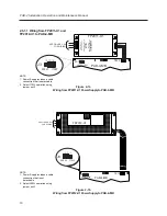
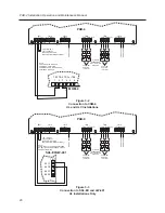
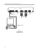
2.6.1.1 Wiring from FP2011-U1 and
FP2012-U1 to PAD-4-MB
FP2011-U1
TB10
+24V (Red)
(Blk)
Brownout
(Blue)
GND (Blk)
PSSI
PAD-4-MB
SEE FIGURE 2-6a
FOR WIRING
LN
G
A
V
ANT
ENTRETIEN
DESACTIVEZ
L
'UNITE
REMOVING
TERMINAL
BLOCK
PROTECTION
DISCONNECT
POWER
PRIOR
T
O
W
ARNING
Brownout PSSI GND +24V
170W
J3
300W
170W
J3
300W
Figure 2-7a
Wiring from FP2011-U1 Power Supply to PAD-4-MB
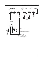
FP2012-U1
H
N
G
SEE FIGURE 2-6b
FOR WIRING
1 2 3 4
TB10
PAD-4-MB
Brownout PSSI GND +24V
300W
J3
300W
170W
J3
170W
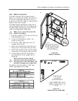
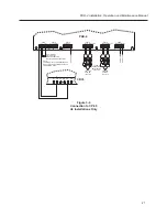
Figure 2-7b
Wiring from FP2012-U1 Power Supply to PAD-4-MB
NOTE:
1. Power Supply includes a cable
connection that is not
detachable.
2. Select 300W operation using
jumper on J3.
NOTE:
1. Power Supply includes a cable
connection that is detachable.
2. Select 170W operation using
jumper on J3.

