GAMMA
instabus
Technical Product Information
March 2014
IP Router N146/02
5WG1 146-1AB02
Technical Manual
N 146/02, 8 pages
Siemens AG
Infrastructure & Cities Sector, Building Technologies
Update: http://www.siemens.com
ã
Siemens AG 2014
Control Products and Systems
Subject to change without prior notice
P.O.Box 10 09 53, D-93009 Regensburg
2.11.1.13/2
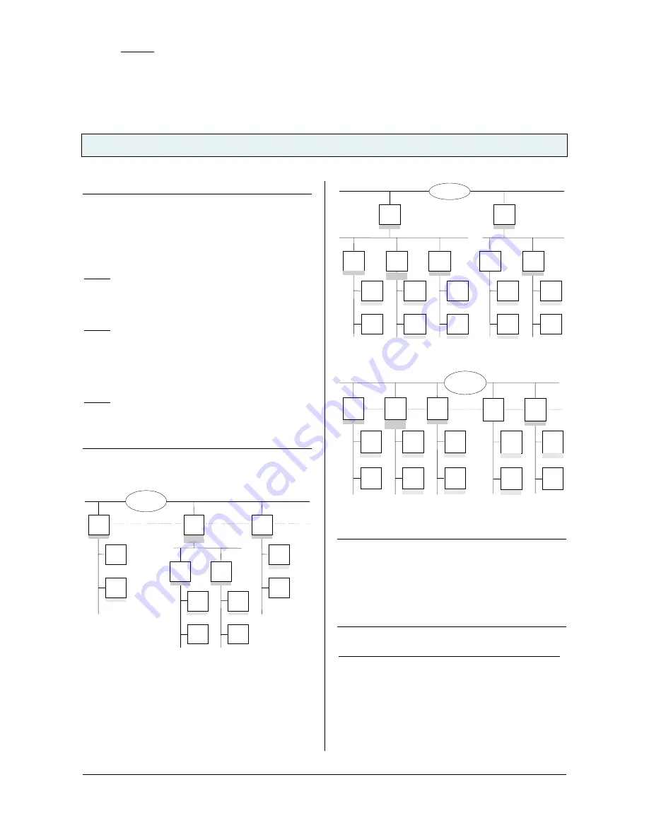
Note
When assigning the physical address take care that IP
Router and line couplers receive the topologically correct
physical address (Fig. 1, IP Router as area coupler and
line coupler).
Adhere to these rules:
Rule 1:
In general an IP Router is used as a line coupler or an
area coupler. The physical address has the format x.y.0,
with x=1…15, y=1…15.
Rule 2:
If an IP Router is applied as an area coupler with the
physical address x.0.0 then no other IP Router with the
line coupler address x.y.0 (y=1…15) shall be placed
topologically „below“ this IP Router (Fig. 2, IP Router
N 146 as area coupler).
Rule 3:
If an IP Router is applied as a line coupler (e.g. with
physical address 1.2.0) then no other IP Router shall be
used with a superior area coupler address (e.g. 1.0.0) in
this installation (Fig. 3, IP Router N 146 as line coupler).
Line
Coupler
2.1.0
Line
Coupler
2.2.0
Device
1.1.1
Device
1.1.2
Device
2.1.1
Device
2.1.2
Device
2.2.1
Device
2.2.2
4/1/1
4/1/1
5/5/1
Main Line 2
4/1/1
IP Network
EIBnet/IP
Router
1.1.0
EIBnet/IP
Router
2.0.0
IP
KNX
Device
3.3.1
Device
3.3.2
EIBnetIP
Router
3.3.0
4/1/1
4/1/1
5/5/1
5/5/1
5/5/1
5/5/1
Figure 1. IP Router as area and line coupler
EIBnet/IP
Router
1.0.0
IP Network
EIBnet/IP
Router
2.0.0
Main Line 1
Main Line 2
Line
Coupler
1.1.0
Line
Coupler
1.2.0
Line
Coupler
1.3.0
Line
Coupler
2.1.0
Line
Coupler
2.2.0
Device
1.1.1
Device
1.1.2
Device
1.2.1
Device
1.2.2
Device
1.3.1
Device
1.3.2
Device
2.1.1
Device
2.1.2
Device
2.2.1
Device
2.2.2
4/1/1
4/1/1
4/1/1
5/2/1
5/2/1
4/1/1
4/1/1
4/1/1
4/1/1
4/1/1
5/2/1
5/2/1
5/2/1
6/3/1
6/3/1
IP Network
Figure 2. IP Router as area coupler
Device
1.1.1
Device
1.1.2
Device
1.2.1
Device
1.2.2
Device
1.3.1
Device
1.3.2
Device
2.1.1
Device
2.1.2
Device
2.2.1
Device
2.2.2
4/1/1
4/1/1
4/1/1
5/2/1
5/2/1
4/1/1
4/1/1
4/1/1
5/2/1
5/2/1
5/2/1
6/3/1
6/3/1
IP Network
EIBnet/IP
Router
2.2.0
EIBnet/IP
Router
2.1.0
EIBnet/IP
Router
1.1.0
EIBnet/IP
Router
1.2.0
EIBnet/IP
Router
1.3.0
IP
KNX
Figure 3. IP Router as line coupler
Note
Smooth operation of the IP Router as line coupler or
back-bone coupler using KNXnet/IP Routing requires
LAN network components that support IP multicasting.
In particular, network / LAN routers must be configurable
respectively configured to forward IP multicast
datagrams.
The IP multicast address 224.0.23.12 was specifically
reserved for KNXnet/IP internationally for this purpose.
IP Router as interface to the bus (KNXnet/IP Tunneling)
A direct connection between a networked PC and the
bus can be established via a data network and the IP
Router. This allows for accessing the bus from any
access point in the data network.
The IP Router N146/02 provides up to four KNXnet/IP
Tunneling connections, allowing for e.g. simultaneous
configuration with ETS3 and operation of a visualization.


