26/49
A6V10336897_d_en_
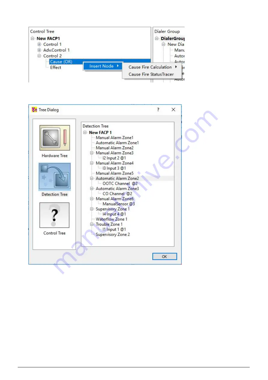
“Cause Fire Status Tracer” is used to add a device/zone.
3. When select “Cause Fire Status Tracer”, the “Tree Dialog” window is displayed. From the Tree Dialog,
select “Detection Tree” from the left side. All zones under the detection tree will be listed on the right side.
Select “Automatic Alarm Zone 2” and click “OK”, the “Automatic zone 2” is then displayed under the
“Cause (OR)” of Control 2.
4. Add “Automatic Alarm Zone 3” to “Cause (OR)” under Control 2 as in Step 3.
5. Assign “O2 Output 2 @1” to “Effect” under Control 2.
6. Change the “Cause Calculation” property to “AND” from the property view of the “Cause (OR)” under
Control 2. The new control logic is now created.
NOTE
·
FXS901 software provides an easy way to assign a device/zone to control tree from detection tree
and hardware tree. Select one device/ zone and drag to control tree and release directly, the
assignment is finished.
·
Only one Releasing control can be assigned to one LED control.
Summary of Contents for FC901-U3
Page 1: ...A6V10336897_d_en_ 2019 12 10 Smart Infrastructure FXS901 User Manual ...
Page 30: ...FXS901 User Manual A6V10336897_d_en_ 29 49 ...
Page 37: ...36 49 A6V10336897_d_en_ 4 When the following window is displayed click OK to close it ...


