background image

Extensions: D992 dual

10 - English

A26361-D992-Z121-2-7419

Extensions: D992 dual

1

2

3 4

5

6

7

8

9

10

11

12

13

14

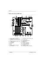
1 = Main memory bank 3
2 = Main memory bank 2
3 = Main memory bank 1
4 = Main memory bank 0
5 = Voltage converter for processor 1
6 = First processor
7 = Second processor (optional)

8 = Voltage converter for processor 2
9 = Lithium battery
10 = Flash BIOS
11 = ISA slots - from below: 1 and 2
12 = PCI slots (from below: 2, 3, 4, 5, 6, 7)
13 = Video memory 1 Mbyte (optional)
14 = Video memory 1 Mbyte

i

PCI slots 2, 3 and 4 are connected to the primary PCI bus. PCI slots 5, 6
and 7 are connected to the secondary PCI bus.
PCI slot 7 is only for short boards.

Summary of Contents for D992

Page 1: ...Systembaugruppe D992 System board D992 Technisches Handbuch Technical Manual ...

Page 2: ...ieses Handbuches Siemens AG Redaktion OEC BS2 OS ID4 Otto Hahn Ring 6 D 81730 München Is there any technical problem or other question you need clarified Please contact one of our IT Service Shops your sales partner your sales office The addresses of our IT Service Shops can be found in the guarantee coupon booklet The latest information on our products tips updates etc can be found on the Interne...

Page 3: ...per Fax 089 636 42945 Oder schreiben Sie an Siemens AG Training Center Beratungsservice D 81730 München Your training needs The Siemens Training Centers offer you a wide range of training courses in information technology and on IT products and other subjects onsite near to your workplace or offsite at one of our training centers Contact us for information on consulting course schedules and selfst...

Page 4: ...esto manuale è stato stampato su carta da riciclaggio Denna handbok är tryckt på recyclingpapper Dit handboek werd op recycling papier gedrukt Herausgegeben von Published by Siemens AG D 81730 München Bestell Nr Order No A26361 D992 Z121 1 7419 A26361 D992 Z121 1 7419 A26361 D992 Z121 1 7419 A26361 D992 Z121 1 7419 Printed in the Federal Republic of Germany AG 0798 07 98 A26361 D992 Z121 1 7419 ...

Page 5: ...Systembaugruppe D992 System board D992 Technisches Handbuch Technical Manual Deutsch English Ausgabe Juli 1998 July 1998 edition ...

Page 6: ...e für den Fall der Patenterteilung oder GM Eintragung Liefermöglichkeiten und technische Änderungen vorbehalten Intel and Pentium are registered trademarks and MMX and OverDrive are trademarks of Intel Corporation USA Microsoft MS MS DOS and Windows are registered trademarks of Microsoft Corporation PS 2 and OS 2 Warp are registered trademarks of International Business Machines Inc All other trade...

Page 7: ...no 11 Upgrading main memory 12 Replacing the Pentium II 12 Upgrading the video memory 14 Replacing the lithium battery 15 Settings in SCSI Setup 16 Setting SCSI addresses IDs 16 Connecting SCSI devices 16 SCSI Setup 17 Starting the SCSI Setup 17 Terminating the SCSI setup 18 Default Settings in the SCSI setup 19 SCSI Bus Interface Definitions 20 Host Adapter SCSI ID 20 SCSI Parity Checking 20 Host...

Page 8: ......

Page 9: ...onal conventions The meanings of the symbols and fonts used in this manual are as follows Pay particular attention to texts marked with this symbol Failure to observe this warning endangers your life destroys the system or may lead to loss of data i This symbol is followed by supplementary information remarks and tips Ê Texts which follow this symbol describe activities that must be performed in t...

Page 10: ... concerning special waste Connecting cable for peripherals must be adequately insulated to avoid interference Modules can become very hot during operation Make sure you do not touch modules when adding components to the system board There is a danger of burns i The warranty expires if the device is damaged during the installation or replacement of system expansions Information on which system expa...

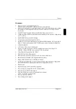
Page 11: ...rocessor and extended cacheability 4 Mbit Flash BIOS 6 PCI slots 2 ISA slots 1 slot shared Screen controller connected to PCI bus graphics processor Cirrus Logic CL GD5446 1 Mbyte DRAM video memory 2 Mbyte optional Ultra Wide SCSI controller AIC 7880P SNI ASIC for Server Management IDE hard disk controller connected to PCI bus for two IDE drives Real time clock calendar with integrated battery bac...

Page 12: ...rature sensor for processor 2 4 Voltage converter for processor 2 5 Control panel 1 6 Loudspeaker 7 Fan 2 8 Fan 1 9 Server management support 10 IDE drives 11 Temperature sensor for processor 1 12 SCSI indicator 13 Ultra wide SCSI drives 14 Diskette drives 15 Modem On 16 CAN bus controller 1 17 CAN bus controller 2 18 Keyboard and mouse 19 Serial port 1 and 2 20 Parallel port and monitor port ...

Page 13: ...essor 3 Voltage converter for processor 4 Control panel 1 5 Loudspeaker 6 Fan 2 7 Fan 1 8 Server management support 9 IDE drives 10 SCSI indicator 11 Ultra wide SCSI drives 12 Diskette drives 13 Modem On 14 CAN bus controller 1 15 CAN bus controller 2 16 Keyboard and mouse 17 Serial port 1 and 2 18 Parallel port and monitor port ...

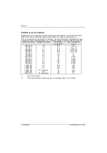
Page 14: ...lied with the controller Screen resolution Refresh rate Hz Horizontal rate kHz Max number of colors 640x350 70 31 5 16 640x480 60 31 5 16777216 640x480 75 37 5 16777216 640x480 85 43 4 16777216 640x480 100 50 6 16777216 720x400 70 31 5 16 720x400 84 38 16 800x600 60 38 65536 800x600 72 48 65536 800x600 75 47 65536 800x600 85 53 7 65536 800x600 100 63 65536 1024x768 60 48 4 256 1024x768 75 60 256 1...

Page 15: ...PT1 IRQ7 Real time clock RTC IRQ8 free IRQ9 free IRQ10 free IRQ11 Mouse controller IRQ12 Numeric processor IRQ13 IDE controller free IRQ14 free IRQ15 assigned IRQ interrupts assigned as shipped i Note that an interrupt cannot be used by two ISA boards or onboard controllers at the same time The screen controller of the system board does not require interrupt IRQ9 If you are using a different scree...

Page 16: ...PEN OFF ON 1 2 3 4 5 6 7 8 Switch 1 System BIOS recovery Switch 2 must be set to off Switch 3 Write protection for system BIOS Switch 4 write protection for floppy disk drive Switch 5 6 7 8 clock speed i The switch settings apply both to the dual processor system and to the monoprocessor system ...

Page 17: ...ried out write protection for the system BIOS must also be disabled in the BIOS Setup in the Security menu the Flash Write field must be set to Enabled If you wish to update your system BIOS please consult our customer service OFF System BIOS can be overwritten default setting ON System BIOS is write protected Write protection for floppy disk drive switch 4 Switch 4 is used to define whether flopp...

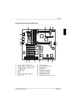
Page 18: ...ter for processor 1 6 First processor 7 Second processor optional 8 Voltage converter for processor 2 9 Lithium battery 10 Flash BIOS 11 ISA slots from below 1 and 2 12 PCI slots from below 2 3 4 5 6 7 13 Video memory 1 Mbyte optional 14 Video memory 1 Mbyte i PCI slots 2 3 and 4 are connected to the primary PCI bus PCI slots 5 6 and 7 are connected to the secondary PCI bus PCI slot 7 is only for ...

Page 19: ...essor 6 Voltage converter for processor 7 Terminating board 8 Lithium battery 9 Flash BIOS 10 ISA slots from below 1 and 2 11 PCI slots from below 2 3 4 5 6 7 12 Video memory 1 Mbyte optional 13 Video memory 1 Mbyte i PCI slots 2 3 and 4 are connected to the primary PCI bus PCI slots 5 6 and 7 are connected to the secondary PCI bus PCI slot 7 is only for short boards ...

Page 20: ...the location Ê At the same time flip the lateral holders upwards until the memory module snaps in place Removing a memory module Ê Flip the holders to the right and left of the location outwards Ê Pull the memory module out of its location Replacing the Pentium II System board D992 dual The system board can be upgraded with a second Pentium II processor in slot 2 You can replace the Pentium II pro...

Page 21: ...the slot if necessary Installing the Pentium II Ê Remove the terminating board if necessary Ê Place the Pentium II in the holder B Ê Push the Pentium II down in the holder and press it into the slot until the clamps A to the left and right snap into place Ê Set the clock frequency of the new Pentium II using switches 5 to 8 of the switch block Ê If the Pentium II has a temperature sensor attach th...

Page 22: ...he video memory up to 2 Mbytes Information on which DRAM components you can use is available from your sales office or the customer service Note the location of the DRAM chip when you plug in DRAM chip A Ê Insert the DRAM component in such a way in the socket for video memory that the mark on the upper side of the DRAM component A matches the position of the mark on the socket ...

Page 23: ...ended by the manufacturer CR2032 Do not throw lithium batteries into the trashcan It must be disposed of in accordance with local regulations concerning special waste Make sure that you insert the battery the right way round The plus pole must be on the top 1 2 3 Ê Lift the contact 1 a few millimeters and remove the battery from its socket 2 Ê Insert a new lithium battery of the same type in the s...

Page 24: ...SCSI ID 0 has the lowest The priority of the remaining IDs in descending order is 15 to 8 Ê Ensure that each SCSI device is assigned it s own address Details how you set the SCSI address of your SCSI devices may be found in the associated manual Connecting SCSI devices SCSI devices and controllers are connected together via a common cable SCSI bus The termination terminating resistors must be enab...

Page 25: ... the SCSI controller and the connected SCSI devices When you boot the system a SCSI BIOS message listing the SCSI devices connected is displayed i If an SCSI BIOS error message appears or problems arise with SCSI devices please refer to the chapter entitled Eliminating errors on the SCSI controller and SCSI BIOS messages You may find further information in the documentation of your SCSI device If ...

Page 26: ...isplay between color and monochrome mode Also note the status line at the bottom of the screen Terminating the SCSI setup Depending on the current menu level you can display the previous menu by pressing the ESC ESC ESC ESC key If you have made changes in the current menu you will be prompted to store them Ê Keep pressing ESC ESC ESC ESC until you arrive at the first menu Configure View Host Adapt...

Page 27: ...es Initiate wide negotiation Yes Send Start Unit Command Yes Include in BIOS Scan Yes Advanced Configuration Options Default setting Reset SCSI Bus at IC Initialization Enabled Host Adapter BIOS Enabled Support Removable Disks Under BIOS as Fixed Disks Boot only Extended BIOS Translation for DOS Drives 1 Gbyte Enabled Display Ctrl Ctrl Ctrl Ctrl A A A A Message During BIOS Initialization Initializ...

Page 28: ... Disabled Parity checking is disabled i If parity checking is disabled this applies to all SCSI devices on the SCSI bus Host Adapter SCSI Termination If the ultra wide SCSI controller is the last device on the SCSI cable its termination must be enabled If the ultra wide SCSI controller is not the last device on the SCSI cable its terminator must be disabled LowON HighON The termination is enabled ...

Page 29: ...ous mode if it receives a request from one of your SCSI devices It can however also exchange data with slow SCSI devices Yes The function is enabled default entry No The function is disabled i Synchronous data transfer is required for fast and ultra SCSI operation Initiate wide negotiation This option determines whether the SCSI controller attempts 16 bit data transfer Wide SCSI instead of 8 bit d...

Page 30: ... to start several drives simultaneously or for preventing switchon current peaks You may have to make settings on your SCSI devices to enable support for this function see the documentation for the SCSI devices Yes The function is enabled default entry No The function is disabled Include BIOS Scan The SCSI device can be used as the boot drive if this function is enabled The SCSI device is accessed...

Page 31: ...a drive designated as the boot device is treated as a hard disk default setting All Disks All removable media drives supported by the BIOS are treated as hard disk drives Disabled No removable media drives are treated as hard disk drives In this situation software drivers are needed because the drives are not controlled by the BIOS If a removable media device is controlled by the SCSI controller B...

Page 32: ...will not be used as the startup drive default entry BIOS Support for Bootable CD ROM This option determines for booting from a CD ROM drive Enabled It is possible to boot from the CD ROM default entry Disabled It is not possible to boot from the CD ROM BIOS Support for Int 13 Extensions This option determines whether the SCSI BIOS supports disks with more than 1024 cylinders The default setting is...

Page 33: ...e the hard disk completely and regenerate the error list Eliminating errors on the SCSI controller Most problems with the onboard ultra wide SCSI controller occur when SCSI devices are prepared e g termination and connected to the SCSI bus Check the following points if you have problems with the ultra wide SCSI controller or the connected SCSI devices Are all SCSI devices supplied with power Are t...

Page 34: ...CSI device concerned If the message still appears check the settings required for the SCSI device in its documentation Start unit request failed The SCSI BIOS could not issue a start unit command to the SCSI device Call the SCSI Setup and set Send Start Unit to No for the SCSI device concerned Time out failure during A timeout has occurred Check the SCSI bus termination Remove the SCSI cable from ...

Reviews: