


4
Siemens Building Technologies
Fire Safety & Security Products
04.2009
EN
Details for ordering
Type Item
number
Description
CIL0050-30
S54561-C801-A1
IR lamps 30 – 60°
CAIL0050-PA S54561-B851-A1
PSU adapter for pole mount
CHBS2310
2GF1705-8LE
Aluminum wall mount with integral
swivel-tilt joint
CHBA0211
2GF1705-8LH
Pole adapter for CHBS2310 mounts
Technical data
Power requirements
PSU: 100 – 230 V AC
Power consumption
PSU: 50 W (on max. power)
Fuse
T 2.5 A
Output power
PSU: 2.4 A at 13.5 V
Photoelectric switch relay output
max. 120 V AC / 24 V DC, 1 A
Telemetry input
Control input (no-voltage input,
floating contact)
Camera voltage output
12 V DC / 1 A
Adjustable IR power
10 – 100 %
Angle of light source
30 – 60°
Range
Max. 100 m
Spectral emission
850 nm, Class 1 LED to EN 60825-1
Weight
PSU: 1.65 kg
Illuminator: 2.50 kg
Relative humidity
Approx. 80 %
Ambient temperature, operation
-20 to +50 °C
Ambient temperature, storage
-30 to +60 °C
Dimensions (L x W x D)
PSU: 160 x 160 x 81 mm
Illuminator: 210 x 150 x 63 mm
Protection rating
IP66, IK10 (IR illuminators)
Approvals CE,
C-Tick
MTBF 70.000
h
Cable glands
4 x M16 (min. 4.5 mm, max. 10 mm
cable dia.)
Troubleshooting
Ensure all tests are carried out by a qualified, trained engineer. Ensure
safe working practices are followed at all times.
1.
Basics
•
Check polarity of infrared lamp connection
(
red = lamp+, black = lamp-
).
•
Check if telemetry inputs are linked by bridge.
•
Check if the photoelectric switch is working.
•
Check setting by turning power potentiometer fully clockwise.
•
Check mains input.
•
Check fuse to ensure it is intact.
2.
Set up camera, lens and illumination.
•
Check alignment of lamp.
•
Check camera lens – fully open at night and set correctly.
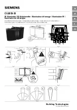
Summary of Contents for CIL0050-30
Page 13: ......