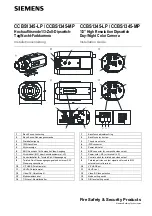
3
Siemens Building Technologies
Fire Safety & Security Products
09.2006
Bestellangaben
Details for ordering
Typ CCBS1345-LP
CCBS1345-MP
Type
CCBS1345-LP
CCBS1345-MP
Bestell-Nr. 2GF1118-8GA 2GF1118-8GB Order
No.
2GF1118-8GA
2GF1118-8GB
Bezeichnung Tag/Nacht-Kamera
12 V DC/24 V AC
Tag/Nacht-Kamera
90 – 260 V AC
Description Day/Night
Camera
12 V DC/24 V AC
Day/Night Camera
90 – 260 V AC
Gewicht
0,45 kg
0,55 kg
Weight
0.45 kg
0.55 kg
Zubehör, nicht im Lieferumfang enthalten
Typ PSU230-12
CAPA2410-P
Bestell-Nr. 2GF1800-8BE
2GF1800-8BJ
Bezeichnung
Netzteil für 12 V
DC
Netzteil für 24 V
AC
Gewicht
0,12 kg
0,30 kg
Accessories, not included in delivery
Type PSU230-12
CAPA2410-P
Order No.
2GF1800-8BE
2GF1800-8BJ
Description
Power supply unit
12 V DC
Power supply unit
for 24 V AC
Weight
0.12 kg
0.30 kg
Lieferumfang
z
CCD-Kamera
z
C/CS-Montageadapter
z
Installationsanleitung
Scope of delivery
z
CCD camera
z
C/CS-mount adapter
z
Installation guide
Installation
Schritt 1: Montage der Kamera
z
Montieren Sie die Kamera an einem Wandarm, Deckenarm oder
Schwenkantrieb. Benutzen Sie dazu das ¼-Zoll-Stativgewinde
(
3
), um ein Verdrehen der Kamera zu verhindern.
z
Montieren Sie die Kabelführung an der Kamera, um
sicherzustellen, dass die Kabel sicher an ihrem Platz gehalten
werden (siehe Abb. A).
Schritt 2: Anbringen des Kameraobjektivs
Wählen Sie eine der folgenden Optionen:
z
Für C-Mount-Objektive: Bringen Sie einen CS-C-Adapter an der
Kamera an und schrauben Sie das Objektiv dann direkt auf die
Kamera.
z
Für CS-Mount-Objektive: Schrauben Sie das Objektiv direkt auf
die Kamera (kein Adapterring erforderlich).
Schritt 3: Anschließen des Objektivs
Für diese Kamera können zwei Arten von Objektiven (DC- oder
videogesteuert) verwendet werden. Wählen Sie jedoch mit dem
Schalter (
12
) DC oder VIDEO, bevor Sie das Objektiv anschließen,
und achten Sie darauf, dass die Verdrahtung für jeden Objektivtyp
der Stiftbelegung unten entspricht.
Videoobjektiv DC-Objektiv
1 +12
V 1 Damp-
2 NC 2
Damp+
3 VIDEO 3 Drive
+
4 Masse 4 Drive-
schließen Sie dann das Steuerkabel am IRIS-Anschluss (
4
, seitlich
oder hinten) der Kamera an.
Schritt 4: Anschließen des Videosignals
z
Für Composite Video: verbinden Sie den BNC-Anschluss
VIDEO OUT (
6
) über ein Koaxialkabel mit dem Monitor.
z
Für TP-Video: Schließen Sie das TP-Kabel am Twisted-Pair-
Videoausgang (
9
) an. Achten Sie auf die korrekte Polarität. Bei
Benutzung des TP-Ausgangs wird am anderen Ende der TP-
Leitung ein TP-Empfänger wie ein TP-RXI1 oder entsprechend
benötigt. Stellen Sie mit dem DIP-Schalter (
8
) DIP 1-4 die
Sendereigenschaften ein:
Installation
Step 1: Mounting the camera
z
Attach the camera to a wall bracket, ceiling bracket, pan/tilt
mount or other suitable fitting. Use the ¼ inch thread tripod
mount hole (
3
) to prevent the camera from rotating.
z
Mount the cable guide to the camera to ensure that the cables
are kept securely in place (see Fig. A).
Step 2: Fitting the lens to the camera
Select one of the following options:
z
For C-mount lens: Add a CS-C adapter to the camera, then
screw the lens directly onto the camera.
z
For CS-mount lens: Screw the lens directly onto the camera
(no adapter ring required).
Step 3: Connecting the lens
Two types of lens (DC- or video-controlled) can be used for this
camera. However, select DC or VIDEO lens using the switch (
12
)
before connecting the lens and make sure the wire connection for
each type of lens is conforming to the pin assignment below.
Video Lens
DC Lens
1 +12
V 1 Damp-
2 NC 2
Damp+
3 VIDEO 3 Drive
+
4 GND 4 Drive-
Then connect the control cable to the IRIS connector (
4
, side or
rear) on the camera.
Step 4: Connecting the video signal
z
For composite video: Connect BNC connector VIDEO OUT (
6
) to
the monitor with a coax cable.
z
For TP video: Connect TP cable to the twisted pair
video output (
9
). Ensure correct polarity. Usage of TP output
requires a TP receiver at the other end of the TP line such as TP-
RXI1 or equivalent. Adjust the transmitter characteristics using
DIP SW (
8
) DIP 1-4:


