background image

AOP Operating Instructions – Issue 07/05 

6SE6400-5AP00-0BB0


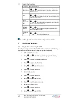
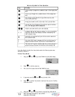
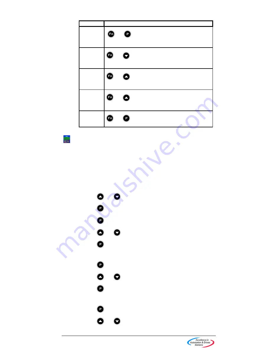
1.1 Special 

Key 

Functions 

Function Keypad 

Strokes 

Main Menu   

 and 

 simultaneously, at any time, will display 

the main menu. 

Help 

 and 

 simultaneously, at any time will display the 

relevant help screens. 

Delete 
Parameter 
Set 

 and 

 when uploading a parameter set is used to 

delete a stored parameter set. 

Software 
Version 

 and 

 when viewing a stored parameter set to 

see the software version. 

Top Level 
Menu 

 and 

 to go to top level menu 


  Is used throughout the manual to indicate a keypad special function. 

2 Applications 

Examples 

2.1 

Single drive control using the AOP 

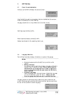
To configure a single inverter with the AOP as the control source, the following 
procedure should be performed to change the required parameters. 

1. 

Fit the AOP to the inverter. 

2. Using   and 

 select the required Language for the display. 

3. Press   to confirm the language selection. 

4. Press   to bypass the Start Help. 

5. Using   and 

 select Parameters. 

6. Press   to confirm selection. 

7. Select 

All 

Parameters. 

8. Press   to confirm selection. 

9. Using   and 

 select P0010 

10. Press   to edit the parameter value. 

11.  Set P0010 access level to 1 

12. Press   to confirm selection. 

13. Using   and 

 select P0700. 

Summary of Contents for AOP

Page 1: ... Help 16 3 4 Normal Operation Screen 16 3 5 Main Menu Local Mode 17 3 6 Wait Request 18 4 Operate Menu 19 4 1 Operating in Local Mode 19 4 2 Operating in Master Mode 20 5 Selecting the Operating Mode 21 5 1 Local Mode 22 5 2 Master Mode 22 5 3 Internal Mode 22 5 4 Slave Mode 22 5 5 PC Mode 22 6 Parameter Access 22 6 1 Standard Level Parameters 22 6 2 Use of Function Key 24 6 3 Expert Level Paramet...

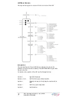
Page 2: ... designed to enhance the interface and communications capability of the MICROMASTER 4th generation frequency inverters For details on the operation of the AOP see the following Sections Section 2 Application Examples Section 3 4 5 AOP First Start up and Mode Selection Section 6 Parameter Access and Controlling the inverter with the AOP Section 7 AOP Set up and Configuration Section 8 Fault Indicat...

Page 3: ...isplayed value as a binary number For a full description of the binary values please see the inverter user guide Inhibit When the AOP displays Inhibit this indicates that the inverter is in an inhibit mode of operation as reported on the USS message This will be cleared when the drive has had a valid start stop command from the AOP On First power up send an OFF1 command to the inverter before tryi...

Page 4: ...hroughout the manual to indicate a keypad special function 2 Applications Examples 2 1 Single drive control using the AOP To configure a single inverter with the AOP as the control source the following procedure should be performed to change the required parameters 1 Fit the AOP to the inverter 2 Using and select the required Language for the display 3 Press to confirm the language selection 4 Pre...

Page 5: ...g will cause the drive to trip if communication with the control source the AOP is lost If you have problems connecting to the inverters set the Auto Baud to OFF and the default baud rate to the same as the inverter See Section 2 5 on page 10 2 2 Network Setup RS 485 With Panel Mounting Kit There are two main modes of operation for the AOP when connected to a network of Micromaster 4th generation ...

Page 6: ...ned a unique RS485 USS address in the range of 0 to 30 To do this set P003 2 and using P2011 assign a unique address to each inverter 3 Set the control over the USS on the communications port Follow the process as in 2 1 above in step 15 set P0700 5 USS on Com link 4 With the drives powered up on the network connect and power up the AOP on the PMK 5 At start up of the AOP select MASTER mode 6 Sele...

Page 7: ...omplete the quick commissioning and the motor identification for the inverter to modify internal parameters level 4 This is important for sensor less vector control To do this set P1910 3 Alternatively the commissioning PC software STARTER may be used to perform upread download completely in order to clone a MICROMASTER 440 Memory Limitation The delivered AOP supports five European Languages of En...

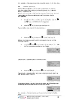
Page 8: ... desired parameter set into which the information will be written If the selected parameter set already contains a parameter set the user will be given the option to clear the existing parameter set Pressing the and keys simultaneously when uploading will delete the existing parameter set When viewing stored parameter sets this same key combination will display the software version number of the u...

Page 9: ...ighlighted 2 Press the key to confirm the selected option The user is then presented with the download menu 3 Press the key to confirm or to cancel the process In Master mode the user would have to select a specific inverter from the networked inverters 4 Using the and keys scroll through the parameter sets of the AOP from which the information is to be written The user will be presented with a co...

Page 10: ...are Version Information P8552 Base slave address P8553 Default baud rate P8564 Enable Autobaud P8560 Battery level P8561 Enable Backlight P8562 Free Memory P8563 Enable Text Scrolling P8564 RS232 Error count P8565 RS485 Error count P8566 Null USS Responses P8567 USS Timeouts 2 6 Slave Mode and operation with DriveMonitor The AOP may be connected to a PC running DriveMonitor Note The default baud r...

Page 11: ... manual It should be noted that the timer settings also use AOP memory This parameter set can then be transferred to a PC using DriveMonitor as described in the previous section 2 8 Timer Operation Notes Before using the Timer function as a control method the user should set the Real Time Clock of the AOP as described in Section 7 1 8 on page 29 Setting a timing event for EVERY DAY will put a sepa...

Page 12: ...ter at that address has been detected by the AOP in Master mode Allows the programmed timing event to be communicated to all connected drives This is the ON symbol indicating that the currently viewed or programmed event is when the inverter will be switched on This is the OFF symbol indicating that the currently viewed or programmed event is when the inverter will be switched off To set the timer...

Page 13: ...The inverter addresses are a numerical value from 0 to 31 for individual inverters These addresses should have been previously set as described in Section 2 2 Network Setup If you wish to send the timed event to all connected inverters then select B which is the broadcast mode 10 Press to confirm the selection and move the cursor to the ON OFF field 11 Using the and keys select either for ON or fo...

Page 14: ... and keys select a blank event screen to set the required ON or OFF time for the inverter depending upon what timing event was previously set 20 To program a new event perform steps 8 through 19 above Ensure that a new blank event screen is selected as any entry in a previous event will overwrite the previously entered data 21 To EXIT from the TIMER screen and save the changes two long presses of ...

Page 15: ... languages Notes Prior to language selection the AOP has no control over the inverter Memory Limitation The delivered AOP supports five European Languages of English German French Spanish and Italian Due to internal memory limitations the user should delete one of these languages in order to upread the specified ten parameter sets that can be held on the AOP To Delete a Language Select Language fr...

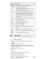
Page 16: ... side of the screen will indicate if more information is available and the direction in which to navigate using the and keys Use the key to return to the previous screen or to move past the help screen onto the main menu Press and simultaneously at any time to return to the main menu 3 4 Normal Operation Screen Once a language has been selected the user is presented with the main menu screen The u...

Page 17: ... Indicates the speed of the motor M 0 Indicates the current torque of the motor V 0 0 V Indicates the output voltage Vdc 0 0V Indicates the dc link voltage Fn T Pressing these keys simultaneously will display the help pages P Pressing P will select the parameter access screen TS Use these keys to scroll through information on the display Indicates the direction of the running motor Pressing and si...

Page 18: ...a parameter set from the inverter into the AOP DOWNLOAD Allows the user to write a parameter set to the inverter LANGUAGE Allows the user to select a new language for the AOP display SETUP Allows the user to personalize the configuration of the AOP TIMER Allows the user to set a start and stop time for the inverters operation Press the and simultaneously at any time will return the user to the mai...

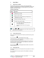
Page 19: ...revious screen Pressing and simultaneously in any screen or sub menu will return the user to the main menu 4 1 1 Communications Failure When communications between the AOP and the inverter fail a warning screen is displayed The user must press to acknowledge the fault condition If a fault occurs again the AOP will assume it is not connected to an inverter The user is then returned to the Main Menu...

Page 20: ...d values P0700 5 P2014 0 5000 P2011 0 Unique number for each drive on the network For more information on setting inverter for network operation see Section 2 2 above Button Function Indicates the inverter is active and communicating Indicates no active slave icon is blank F Indicates an inverter fault has been recorded and the inverter has tripped A Indicates an inverter with active warnings Indi...

Page 21: ...g the Operating Mode The Mode Menu allows the user to select the required operating mode of the AOP The modes supported by the AOP are listed below LOCAL MASTER INTERNAL SLAVE PC mode MM3 Upload see Section 5 To exit a selected mode either follow the on screen instruction or select Mode from the top level menu and change to a different mode of operation A summary of the various modes and their lim...

Page 22: ...ly described In the broadcast mode it is possible only to start and stop the motor directly simultaneously 5 3 Internal Mode In Internal mode the user has access to the AOP s own parameter sets which are store within the AOP s hardware No access is given in this mode to the parameter sets held within the inverter 5 4 Slave Mode In this mode the AOP is configured to communicate with a PC utilizing ...

Page 23: ...r group Once a group is selected the user will be presented with the first parameter in ascending order of numerical value 4 Using the and keys scroll through the parameters until the required parameter is highlighted 5 Press the key to confirm the selected parameter 6 The user is now presented with parameter values Using the and keys the value of the parameter can be changed Note The AOP will onl...

Page 24: ...isplay can be changed by performing the following actions Ensure you are in the parameter value changing level 1 Press which causes the right hand digit to blink 2 Change the value of this digit by pressing or 3 Press again causes the next digit to blink 4 Perform steps 2 to 3 until the required value is displayed 5 Press to leave the parameter value changing level 6 2 3 Jump Function From any par...

Page 25: ...e 4 Using the and keys scroll through the parameters until the required parameter is highlighted 5 Press the key to confirm the selected parameter 6 Press the key again to access the parameter index 7 Using the and keys scroll through the indexes until the required index is highlighted 8 Press the key to access the index value 9 Using the and keys scroll through the values until the required value...

Page 26: ...option screen 3 Using the and keys highlight INTERNAL 4 Press the key to confirm the selected option The user is then presented with the Internal mode menu screen 5 Using the and keys highlight PARAMETERS The user is then presented with the internal edit menu for the AOP 6 Using the and keys highlight required parameter set number The parameters can now be edited using the procedures outlined in S...

Page 27: ...acklighting To activate the backlighting option on the AOP the following procedure should performed 1 Using the and keys select the Backlighting option from the Setup menu 2 Press to confirm the selection The user is then presented with the Backlighting screen 3 Using the and keys select either the off or on state 4 Press to confirm the selected function The backlighting function can be set to swi...

Page 28: ... required cursor is highlighted 2 Press to confirm the action and return to the Setup menu Pressing the and keys simultaneously at any time will display the relevant help screens to assist the user 7 1 5 Start Help By default the Start Help function is set to ON To change this setting select Start Help from the Setup menu 1 Using the and keys select either the Off or On state 2 Press to confirm th...

Page 29: ...elevant help screens to assist the user 7 1 7 Parameter Set Names This function allows the user to edit the parameter set names All ten parameter sets can be edited This option is not available in the standard access level To edit the parameter set names the following procedure should be performed 1 Using the and keys select the Parameter Set Names option from the Setup menu 2 Press the key to con...

Page 30: ... 4 Press the key to confirm the selection The cursor then automatically moves to the minutes field 5 Repeat steps 3 and 4 until the minutes and seconds are set to the correct time The Day Date screen is then displayed 6 Complete steps 1 to 5 above to set the correct Day Date 7 Press and hold the key to accept the Day Date settings and return to the Setup menu 7 1 9 AOP Reset Warning This function ...

Page 31: ...the deletion of the inverter parameter sets stored within the AOP s memory Or Press to perform the AOP reset without deleting the inverter parameter sets stored within the AOP s memory Caution The AOP reset function will return all internally stored AOP specific data to its factory default settings this includes such functions as the timer control settings etc Pressing the and keys simultaneously ...

Page 32: ...t have been set as the command source P0700 4 or 5 Or Pressing the and keys simultaneously will display warning specific help screen as an aid to diagnosing the problem Note The AOP can only clear the fault if P0700 has been set so that the AOP has control of the inverter 8 2 Warning Screen The AOP has been designed to display a warning screen should a condition arise within the connected inverter...

Page 33: ...cle will repeat itself until all fault messages have been either acknowledge or clear and the conditions causing the warning messages have ceased to exist For instructions on how to acknowledge the fault messages see Section 9 1 8 6 Inverter Fault Codes When a fault occurs on the inverter s to which the AOP is connected a fault code is displayed with a description of the relevant fault For a compl...

Page 34: ... presented with one of the following screens If no fault history exists If a fault history exists 3 If no fault history exists then press or to return to the Main Menu 4 If a fault history exists use the and keys to scroll through the fault history 5 Press the and keys simultaneously to display the help screen which will contain details of the relevant corrective action 6 Press and hold down the k...

Page 35: ...35 AOP Operating Instructions Issue 07 05 6SE6400 5AP00 0BB0 NOTES ...

Page 36: ...y Requirements of the directive when used in a typical machine application A Declaration of incorporation is available on request European EMC Directive When installed according to the recommendations described in this guide the MICROMASTER fulfils all requirements of the EMC Directive as defined by the EMC Product Standard for Power Drive Systems EN50082 2 Underwriters Laboratories MICROMASTER 4 ...

Reviews: