
6
ENG
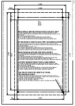
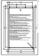
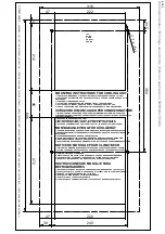
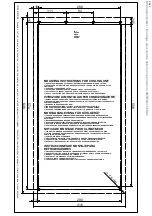
1. Cooling unit application.
The cooling units described in this manual are
designed and built to cool the air inside
switchboards in order to protect components
sensitive to thermal shock and, at the same
time, providing an IP54 protection level against
the infiltration of contaminating and strong sub-
stances.
2. Updates.
The manufacturer reserves the right to update
its product and relative manuals based on tech-
nical progress without prior notice. Please note
that at the time of sale, this manual and relative
product cannot be considered inadequate only
because they are not subject to above-
mentioned updates.
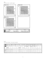
3. Technical features.
(Figures
F.7.1
and
F.10.1
)
4. Supply.
Inside the packaging you will find:
1
1
1
1
6
6
6
1
1
2
cooling unit
installation, operating and maintenance
manual with CE conformity certificate
test certificate
drilling template
M6 nuts
6.4x18 mm flat washers
M6x35 mm dowels
10x5 mm self-adhesive sealing strip
piece of flexible hose for discharging
condensate 12x2x100 mm
M6 eyebolts
…
(figure
F. 19.1
)
(figure
F. 31.1
)
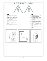
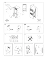
5. Prior to assembly.
•
During transport and storage the cooling
unit must be kept in the position clearly in-
dicated on the packaging (figure
F.1.0
),
and must not be exposed to temperatures
higher than 70°C.
•
Upon receipt, check the packaging has not
been damaged during shipping.
•
Ambient air temperature, where the enclo-
sure is to be installed, must be no higher
than 50°C and should never exceed the
cooling unit’s maximum operating tem-
perature which is specified on its rating
plate. The unit must be positioned far away
from heat sources and flows of hot air.
•
Make sure switchboard protection level is
IP54 or higher. Should this not be the case
excessive condensation could form. Con-
sequently seal well all areas where cables
pass and all other openings in the enclo-
sure.
•
Check that the external environment does
not contain excessive concentrations of
contaminating solids and/or strong chemi-
cals.
•
Check that the flows of air leaving and en-
tering the cooling unit are not obstructed
by walls or objects that are too close. For
this purpose, in the case of the external air
flow, verify the minimum distances (figure
F.2.1
), while in the case of the internal air
flow, make sure there are no obstructions
caused by the switchboard components.
•
The supply voltage available must corre-
spond to the features given on the cooling
unit’s rating plate.
•
The cooling unit must be installed in the
position indicated. Maximum permitted de-
viation from the vertical is 2°.
•
The cooling unit must be installed with the
enclosure air suction hole in the highest
possible point.
•
If the cooling unit has to be installed on a
door, make sure the door can take the
weight.
•
Before making the holes and slits on the
enclosure make sure the fixing elements
and couplings will not interfere with the
equipment inside the enclosure itself.
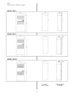
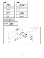
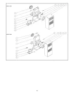
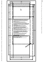
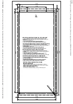
6. Assembly.
Disconnect power before starting any work in-
side the switchboard. The cooling unit can be
applied externally to, or semi-recessed (figure
F.13.1
) on the electric enclosure as preferred
without the need for any additional accessories
(just those you will find inside the standard kit
supplied with the unit). Depending on the in-
stallation type chosen, drill the holes and make
the necessary cuts on the switchboard (figure
F.16.1
) using the drilling template supplied with
the unit.
Fit the sealing strip on the cooling unit
on the side connected to the enclosure and fol-
low the assembly diagram (figure
F.19.1
).
To lift the cooling unit in a safe manner the two
M6 eyebolts may be used fitted into the
threaded inserts located on the top of the cool-
ing unit (figure
F. 4.1
).
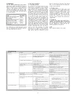
7. Condensate discharge hose.
The condensate which, depending on the am-
bient temperature and humidity conditions,
forms on the exchanger that cools the enclo-
sure air, is not a malfunction but a normal phe-
nomenon of the cooling unit. The condensate is
taken outside through a hose at the bottom of
the cooling unit. The transparent plastic hose,
supplied with the unit, must be connected to
this discharge (figure
F.31.1
).
This plastic hose can be connected to another
one with the same diameter to carry the con-
densate to another point so when it is dis-
charged it is where there can be no slipping
hazard for personnel. In this case, make sure
the condensate flows without any hindrance.
Avoid horizontal lengths of more than 0.5 me-
tres, lengths with a reverse gradient and the
accidental formation of traps (figure
F.22.1
).
The end of the condensate discharge hose
must always be free, never immersed, so never
place the end of the discharge hose inside con-
densate collection trays (figure
F.25.1
).
If the cooling unit is used with the doors of the
enclosure open, excessive quantities of con-
densate will form and this is an unauthorised
condition of use (figure
F.28.1
).
We suggest using a position switch on the door
that will stop the cooling unit if the door is
opened.
8. Electrical connection.
8.1 Safety
Attention! The electrical connection must be
done by specialised and authorised person-
nel. Switch power off to the enclosure be-
fore making the connection.
Check that the available supply voltage corre-
sponds to the characteristics given on the cool-
ing unit’s data plate. The supply of electricity to
the cooling unit must be protected by an isolat-
ing device / fuse or circuit breaker with a dis-
tance between the contacts of at least 3 mm
when open according to the indicated settings
(figure
F.10.1
).
Wire to the terminal board following the instruc-
tions on the wiring diagram and paying attention
to the terminals. After a stop the cooling unit
must not be started again immediately. For this
reason we suggest using a timed control that
delays restarting 3 minutes. Disconnect the
cooling unit before electrically testing the enclo-
sure.
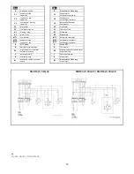
8.2 Versions with an autotransformer
(8MR6423-5EG06 / 8MR6423-5EG08)
These bi-phase versions are set for two supply
voltages: 440V 2~ 50-60Hz and 400V 2~ 50-
60Hz. If the available power supply voltage is
440V 2~ 50-60Hz connect terminals L1(0) and
L2(440) indicated on the adhesive label above
the terminal board located on the rear of the
cooling unit (figure
F.27.0
). If the available
power supply voltage is 400V 2~ 50-60Hz con-
nect L1(0) and L2(400) to same terminal board.
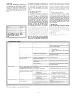
9. First start up and adjustment.
If, prior to installation, the cooling unit was left in
an incorrect position (figure
F.1.0
), wait at least
8 hours before switching it on otherwise 30
minutes are more than enough for the oil to re-
turn to the compressor after which the cooling
unit can be powered. The enclosure air suction
fan starts working immediately, rendering the
temperature even inside the enclosure. If this
temperature is higher than the threshold value
set on the adjustment thermostat both the com-
pressor and external air fan start working, caus-
ing the cooling cycle to start. The latter stops
when the inside temperature reaches the low
limit of the operating differential that has a fixed
value of 4 K. The thermostat is factory set at 35
°C.
To alter this set value access the thermo-
stat, situated at the back of the cooling unit,
from the inside of the electric enclosure (figure
F.33.0
).
With the graduated scale, from 20 to 46
°C, you may alter the set temperature as
wanted. To save energy and minimise the pro-
duction of condensation we recommend not to
go below 30 °C.
9.1 Electronic thermostat (optional)
9.1.1 Setting the set point
Press key P and then release it, the SET LED
turns on and the display shows the SET POINT.
If necessary, use the UP key to increase the
value or the DOWN key to reduce it. These
keys act in one-digit steps but if you keep them
pressed for more than two seconds the value
increases or drops quickly to reach the value
wanted. This mode is exited automatically if you
fail to press any keys for about 5 seconds: the
display returns to displaying the probe meas-
ured temperature.
1
2
3
4
1
4
5
5