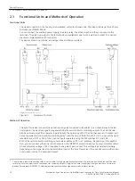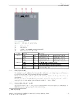
As standard, the Sync Transceiver operates in 2-channel mode. In this mode, the DIP switch S1/3 is in the
Open position. The optical input signals are forwarded to the semiconductor switch contacts on X1 using
separate channels:
•
Channel 1: R1 → X1/1, X1/3
•
Channel 2: R2/BI 2 → X1/8, X1/4
6
NOTICE
DIP switch position S1/2 in 2-channel mode
Disregarding the DIP switch position blocks device operation.
²
If, in 2-channel mode, you use BI 2 instead of R2 as the input, you must set the light idle state mode
of R2 to OFF.
²
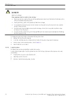
To do this, set the DIP switch S1/2 to the Open position (refer to
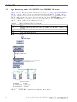
As an alternative, you can also switch the Sync Transceiver to the channel pairing mode. In this mode, the DIP
switch S1/3 is in the Closed position. In the channel pairing mode, the signals of any input (R1, R2, or BI 2) are
transmitted to both semiconductor switching outputs simultaneously. This doubles the number of protection
devices that can be connected to each Sync Transceiver when these devices process the signal of a common
time-synchronization source.
NOTICE
DIP switch position S1/3 in the channel pairing mode.
Disregarding the DIP switch position can lead to the output signals being superimposed.
²
In the channel pairing mode, connect only one single input (R1, R2, or BI 2) to one time-protocol
source because the connection of several sources leads to the going signals being superimposed.
²
If you do not use an optical input, you must configure this optical input to light idle state = OFF.
²
To do this, set the DIP switch S1/3 to the Closed position (refer to
The LEDs RCV1 and RCV2 show the signal activity on channels 1 and 2, typically by blinking, and serve as a
visual check. For time protocols with a higher frequency on the signal levels (for example, IRIG B), the corre-
sponding LED is lit continuously.
6
If the DIP switch S1/4 is in the Closed position, the electronic load disconnecting relay is also activated (X6/1, X6/2).
Device Structure
2.1 Functional Units and Methods of Operation
Accessories, Sync Transceiver, Optical/Electrical Converter for Time Synchronization, Manual
15
C53000-G9050-C168-1, Edition 09.2019

