background image

7PG21 Solkor Rf Commissioning 


©2012 Siemens Protection Devices Limited  


 Chapter 6 Page 11 of 21


each current transformer by comparing the secondary current in each phase with the corresponding primary 
current. Check the polarity of the current transformers; the reading of ammeter X in the neutral circuit should be 
negligible compared with the secondary phase-currents. Some current may exist in the neutral circuit due to 
unbalance of primary load current and/or secondary burden.


2.11  Check of secondary connections 

The purpose of these tests is to establish that the secondary wiring between the current-transformers and the 
summation-transformer at each end is in accordance with the particular diagram supplied for the installation.  
However, if load-current is to be used it is unlikely that actual setting-values can be obtained in which event it is 
considered reasonable if suitable readings can be taken to confirm that the feeder ends behave similarly for the 
same fault-condition. Care should be taken that there is a reasonable value of load current available i.e. 25% to 
50% of nominal. 
 
Remove the trip-links. Check that the pilots are connected at each of the feeder and that the padding resistors are 
correctly set. In order to obtain comparable readings at each end the primary-current should remain constant.  
When using load-current this condition can best be approached by taking readings for a given fault-condition at 
each end in turn. With this object in view, initially connect the secondary circuit at each end as shown in Fig. 3a  
(Solkor Rf without isolating transformers) or Fig. 3b  (Solkor Rf with isolating transformers). For a Red-Earth fault-
condition remove the short-circuiting connection from the Red-phase current-transformer at the end of which the 
first readings are to be obtained. Measure the current in the operating-coil of the relay at this end, also the primary 
and secondary currents, and record the readings. Replace the short-circuiting connection across the Red-phase 
current-transformer, and repeat the above procedure at the other end to obtain comparable readings for the Red-
Earth fault-conditions. 
 
In a similar manner, by suitably connecting the current-transformer secondary leads at each end, obtain alternate 
readings at each end for the Yellow-Earth and Blue-Earth fault-conditions. Tabulate the results as shown in table 
5 and compare results between ends. 


Tripping relay current (mA d.c.) 

Type of fault 

Primary current 

(A) 

Secondary 
current (A) 

Feeder end 1 

Feeder end 2 

R-E 


Y-E 


B-E 


Table 5 - check of secondary connections using 3 Phase load current 

Summary of Contents for 7PG21 Solkor Rf

Page 1: ...Answers for energy 7PG21 Solkor Rf Feeder Protection Reyrolle Protection Devices ...

Page 2: ...es Limited nor shall any model or article be reproduced from this document unless Siemens Protection Devices Limited consent While the information and guidance given in this document is believed to be correct no liability shall be accepted for any loss or damage caused by any error or omission whether such error or omission is the result of negligence or any other cause Any and all such liability ...

Page 3: ...d nor shall any model or article be reproduced from this document unless Siemens Protection Devices Limited consent While the information and guidance given in this document is believed to be correct no liability shall be accepted for any loss or damage caused by any error or omission whether such error or omission is the result of negligence or any other cause Any and all such liability is discla...

Page 4: ...ts Positive half cycle 8 Figure 7 Through Fault 1000 ohm pilots Positive half cycle 8 Figure 8 Through fault Rf mode positive half cycle 9 Figure 9 Through fault Rf mode negattive half cycle 9 Figure 10 Through fault Rf mode positive half cycle 10 Figure 11 Through fault Rf mode positive half cycle 10 Figure 12 Internal fault Rf mode positive half cycle 11 Figure 13 Internal fault Rf mode positive...

Page 5: ...features High transient stability High speed operation Low phase and earth fault settings Little or no variation of settings with pilot length In zone bleed off of up to 20 of rated load Easy to install commission and maintain 15kV pilot isolation option Easily reconnected as either Solkor Rf or Solkor R Pilot Supervision schemes available Remote end injection intertripping via pilot cores availab...

Page 6: ...linear resistors are used to limit the voltage appearing across the pilots and the operating element The purpose of the padding resistors at each end is to bring the total pilot loop resistance up to a standard value The protection is therefore always working under constant conditions and its performance is to a large extent of the resistance of the pilot cable The padding resistors comprise five ...

Page 7: ...the tripping and alarm circuits the installation and commissioning of the equipment is extremely simple To check the current in the operating element a test point is provided The 15kV arrangement is for applications where the voltage across the pilot insulation due to induction or a rise in station earth potential are excessive and where consequently the normal 5kV insulation level is not consider...

Page 8: ...ed to give an optimum balance between the demands of fault setting and stability The pilot is shown as a lumped resistor RP The rest of the pilot loop is made up of four resistors Ra and four diodes D1 D2 D5 and D6 The operating elements which are made unidirectional by diodes D3 D4 D7 and D8 are connected in shunt with the pilots During an external fault condition an alternating current circulate...

Page 9: ...ohm padding resistor in each relay and the 1000ohm sum in the pilot circuit is in one leg of the pilot circuit as shown RP Resistors Ra are of greater resistance than the pilot loop resistance Rp and this causes the point of zero potential to occur within the resistors Ra as shown in Figure 5 The voltage across each relaying point B X and C Y throughout the cycle is now always negative This voltag...

Page 10: ...Positive half cycle At the other limiting condition the pilot resistance is a 1000 ohms loop and the circuit will be as shown in Figure 6 Figure 7 with 500 ohms in each leg of the pilot circuit and zero padding resistors As shown in Figure 6 Figure 7 the resultant voltage distribution of this maximum pilot arrangement gives identical voltages across the relay points B X and C Y 2011 Siemens Protec...

Page 11: ...ering now the equivalent Solkor Rf circuit with 1000 ohms in each leg of the pilots as shown in Figure 8 the voltage distribution shows that the bias voltage across the polarising diodes D3 D4 D7 and D8 with this arrangement are effectively identical with the minimum values obtained in the Solkor R arrangement In other words the balance of the full wave comparison gives the same value of bias for ...

Page 12: ...re 11 Through fault Rf mode positive half cycle If the condition of zero pilots is then considered for Solkor Rf i e with 1000 ohms padding in each relay the circuit and voltage distribution are as shown in Figure 10 Figure 11 This shows that the same bias voltages are as obtained in Figure 8 Figure 9 2011 Siemens Protection Devices Limited Chapter 1 Page 10 of 13 ...

Page 13: ...hown in Figure 12 Figure 13 because the diodes in series with the pilots on the positive leg of the circuit will be out of circuit and the measuring element polarising diodes on this leg will be conducting The voltage distribution fore this arrangement shows how with the assumed balanced infeeds no current flows in the pilots and each measuring element is energised via the resistor Ra The single e...

Page 14: ... fed internal fault but only one summation transformer has any output Thus the other summation transformer acts only as an equalising transformer re circulating current through the measuring element as indicated in Figure 14 Figure 15 The voltage distribution shows diagrammatically how in each half cycle the measuring elements are energised via Ra at the energised end and the action of the remote ...

Page 15: ...r only two pilot cores As this device is essentially a transformer it can also be used to reduce the burden imposed by the pilot circuit on the current transformers by changing the impedance levels In addition it provides isolation between the current transformers and the pilot circuit and makes it possible to have the current transformers earthed and the pilots unearthed R Y B N Primary nx turns ...

Page 16: ...d nor shall any model or article be reproduced from this document unless Siemens Protection Devices Limited consent While the information and guidance given in this document is believed to be correct no liability shall be accepted for any loss or damage caused by any error or omission whether such error or omission is the result of negligence or any other cause Any and all such liability is discla...

Page 17: ... Quantity 3 3 Application Limits 3 4 Performance 3 4 1 Solkor R Rf Relay 3 4 2 Pilot Supervision Equipment 4 4 3 Injection Intertripping 5 5 Environment 5 5 1 Temperature 5 5 2 Humidity 5 5 3 IP Ratings 5 6 Mechanical Durability 5 2010 Siemens Protection Devices Limited Chapter 2 Page 2 of 5 ...

Page 18: ...Peak Voltage applied to pilots under fault conditions 300v 450v 450v 330v 225v Maximum current carried by pilots under fault conditions 200mA 250mA 250mA 380mA 500mA Maximum Primary Line Capacitive Charging Current Solidly Earthed System 1 3 times the most sensitive earth fault setting Resistance Earthed System 1 9 times the most sensitive earth fault setting 4 Performance 4 1 Solkor R Rf Relay In...

Page 19: ...ired to operate relay 1 2VA 3VA 4 2 Pilot Supervision Equipment Auxiliary Supply Send End 110 220 240V ac 50 60Hz Receive End 30V dc 50V dc 125V dc 240V dc Burdens AC Supervision Supply 10VA approx AC supply fail relay 3 to 5VA Receive Repeat Relay 1W Contact Arrangements Pilot Supervision Relay B75 1NO self reset Repeat relay B74 2NO 2NC Supervision supply fail relay 2NO 2NC Contact Ratings Type ...

Page 20: ... resistor 5 Environment 5 1 Temperature IEC 60068 2 1 2 Type Level Operating range 10 C to 55 C Storage range 25 C to 70 C 5 2 Humidity IEC 60068 2 3 Type Level Operational test 56 days at 40 C and 95 relative humidity 5 3 IP Ratings Type Level Installed with cover on IP 51 Installed with cover removed IP 30 6 Mechanical Durability Vibration relays comply with BS142 section 2 1 Category S2 Shock r...

Page 21: ...or shall any model or article be reproduced from this document unless Siemens Protection Devices Limited consent While the information and guidance given in this document is believed to be correct no liability shall be accepted for any loss or damage caused by any error or omission whether such error or omission is the result of negligence or any other cause Any and all such liability is disclaime...

Page 22: ...s 5 3 3 Injection Intertripping 5kV or 15kV 5 3 3 1 R mode 5 3 3 2 Rf mode 5 3 4 Overcurrent Guard Relay 6 4 5 15Kv Isolation Voltage 10 5 Pilot Cables 10 6 Pilot Supervision 11 7 Overcurrent Guard Relays 11 8 Injection Intertripping 11 9 Capacitive Charging Currents 12 10 N N1 Setting 12 11 In Zone Tapped Load 12 12 Current Transformer Requirements 13 2010 Siemens Protection Devices Limited Chapt...

Page 23: ...te a protection operation at the remote end The Solkor R Rf relay has an insulation level of 5kV between pilot connections and the local ground to withstand voltages induced on the pilot cable due to coupling with the fault current flowing in a parallel path and to withstand differential ground voltages caused by the flow of fault current This is generally adequate for distribution feeders but for...

Page 24: ...uency 50 60Hz Send or Receive End Insulation level 5 15kV Auxiliary DC supply Guard Relays CT secondary Current Rating Case Styles System Frequency 50 60Hz Not compatible with Intertripping Auxiliary DC supply for numeric types Intertripping Not compatible with Guard Relays 1 way or 2 way intertripping Auxiliary DC supply R or Rf mode Insulation level 5 15kV 2010 Siemens Protection Devices Limited...

Page 25: ...onal isolation requirements at 15kV necessitate that separate units must be used 3 2 2 15kV Schemes 3 2 2 1 Send End 15kV Pilot Supervision Send End relay transformer rectifier 1 per circuit B22 AC Supply Supervision relay 1 per circuit 5kV insulation as this is not connected to the pilots 3 2 2 2 Receive End 15kV B75 relay 1 per circuit B74 relay 1 per circuit Note Although the 5kV scheme utilise...

Page 26: ...s Standard 5kV Plain Solkor Rf Solkor Rf E6 E6 Solkor Rf 15kV Pilots Standard 15kV Plain Solkor Rf Solkor Rf F2 S2 T2 T1 F2 S2 T2 T1 15kV Isolation Transformer 15kV Isolation Transformer E6 E6 BOP BOP E6 E2 AC Supply Supervision Solkor Rf 5kV Pilots 5kV Solkor Rf with Pilot Supervision Solkor Rf B75 B74 5kV Pilot Supervision Send End 5kV Pilot Supervision Receive End B22 E6 E4 E4 E6 2010 Siemens P...

Page 27: ...or Rf 5kV Pilots 5kV Plain Solkor Rf with Overcurrent Guard Solkor Rf ARGUS1 B69 A B C ARGUS1 B69 E6 E6 E6 A B C E6 15kV Pilots 15kV Solkor Rf with Pilot Supervision and Overcurrent Guard 15kV Pilot Supervision Send End 15kV Pilot Supervision Receive End F2 S2 T2 T1 15kV Isolation Transformer F2 S2 T2 T1 15kV Isolation Transformer B75 B74 B22 1 1 2V 1 1 2V E2 AC Supply Supervision BOP BOP E2 A B C...

Page 28: ...ntertripping Solkor R E6 E6 Solkor R Inverter BOP TEC Initiating Contact 1 1 2V Solkor Rf 5kV Pilots 5kV Solkor Rf mode with One Way Injection Intertripping Solkor Rf E6 E6 Solkor Rf Inverter BOP TEC Initiating Contact E2 B34 B34 1 1 2V 2010 Siemens Protection Devices Limited Chapter 3 Page 8 of 15 ...

Page 29: ...7PG21 Solkor Rf Applications Guide 2010 Siemens Protection Devices Limited Chapter 3 Page 9 of 15 ...

Page 30: ...eeder length as a worst case scenario because although an internal fault may have a greater fault current the parallel path will be shorter by definition 5 Pilot Cables The above considerations of insulation and balance between cores it is evident that pilot cables for use with pilot wire current differential feeder protection are required to have special consideration when long lengths and high f...

Page 31: ...lation level to suit The Send End unit and B75 Receive End must have 15kV insulation The B22 Supervision Relay and B74 Repeat Relay are not connected to the pilots directly and no special isolation requirements apply to these devices 7 Overcurrent Guard Relays Overcurrent Guard relays are connected to the same CTs as the Solkor relay The output contact is connected in series with the Solkor Rf suc...

Page 32: ...ging current is reduced The Solkor summation transformer will measure charging current on two phases only and interpret this as a residual differential current for which relay settings are significantly lower than for 3P balanced differential current This issue is compounded in systems which are not solidly earthed because the unfaulted phase voltage may increase leading to increased charging curr...

Page 33: ...4 pt1 class px whose ratio error is limited to 0 25 and these CTs are recommended to meet the above requirements It is recommended that no other burdens should be included in the current transformer circuit but where this cannot be avoided the additional burden should be added to those listed when determining the current transformer output voltage required In addition to the above the secondary ma...

Page 34: ...els VPh 33000 3 19 05kV Fault level per phase 1000 3 333MVA 17 5kA 19 05x10 333x10 I 3 6 F 19 05kV Zs 17 5kA Ω 089 1 10 5 17 10 05 19 3 3 x x ZS Also since X R at the busbar 20 We can evaluate the source impedance R X Tan 1 θ o 87 θ Ω 00544 cosθ S S Z R Ω 0876 1 sinθ S S Z X Primary X R Zs O RL 0 07765 ohms km Primary RL 10 x 0 07765 0 7765Ω Primary XL 0 28978 ohms km XL 10 x 0 28978 j2 8978Ω Prim...

Page 35: ...hapter 3 Page 15 of 15 ZF 0 8309 j3 9854 ohms 2 2 X R Z 2 2 9854 3 8309 0 Z ZF 4 071 ohms Through Fault Current 4 68kA 4 071 19 05x10 I 3 F Through fault current 4 68kA compared to 17 5kA Busbar fault current due to the effect of the line impedance 19 05kV Zs 17 5kA Z 4 68kA L ...

Page 36: ...ticle be reproduced from this document unless Siemens Protection Devices Limited consent While the information and guidance given in this document is believed to be correct no liability shall be accepted for any loss or damage caused by any error or omission whether such error or omission is the result of negligence or any other cause Any and all such liability is disclaimed 2012 Siemens Protectio...

Page 37: ...G21 Solkor Rf Settings 2012 Siemens Protection Devices Limited Chapter 4 Page 2 of 4 Contents 1 Differential Protection settings 3 1 1 Protection Sensitivity 3 1 2 Pilot Resistance 3 2 Pilot Supervision 4 ...

Page 38: ...ot Supervision is fitted the settings will be increased by 20 50 In Rf mode the remote end relay will operate at a similar level to the local relay typically within 10 of quoted setting In R mode the remote end will typically operate at 2 5 times the local end setting Fault settings In Solkor Rf without isolating transformers Solkor Rf with isolating transformers Nominal Typical Nominal Typical Ty...

Page 39: ...7PG21 Solkor Rf Settings 2012 Siemens Protection Devices Limited Chapter 4 Page 4 of 4 2 Pilot Supervision There are no variable settings associated with the Pilot Supervision system ...

Page 40: ...shall any model or article be reproduced from this document unless Siemens Protection Devices Limited consent While the information and guidance given in this document is believed to be correct no liability shall be accepted for any loss or damage caused by any error or omission whether such error or omission is the result of negligence or any other cause Any and all such liability is disclaimed 2...

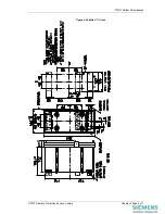
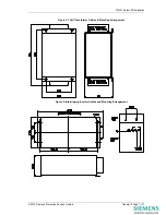
Page 41: ...Vedette Cases 4 4 2 1 Crimps 4 4 2 2 Panel Fixing 4 4 3 Back of Panel cases 4 4 3 1 Crimps 4 4 3 2 Mounting arrangement 4 Table of Figures Figure 1 E2 Case 5 Figure 2 E4 Case 5 Figure 3 E6 Case 5 Figure 4 Vedette C1 Case 6 Figure 5 15kV Transformer Outline Mounting Arrangement 7 Figure 6 Intertripping Inverter Outline and Mounting Arrangement 7 2010 Siemens Protection Devices Limited Chapter 5 Pag...

Page 42: ...on relay in a location more convenient for the connection to the incoming pilot cable and or in the interest of safety Connections to the relay can then be made at the lower 5kV insulation level with precautions and identification to suit 3 Relay Dimensions The Solkor Rf relay is supplied in an Epsilon size E6 case 5kV Pilot Supervision Send and Receive End units are supplied in Epsilon size E4 ca...

Page 43: ...fitted to relay Consists of 28 x M4 8mm Screws 28 x M4 Lock Washer 4 2 Vedette Cases 4 2 1 Crimps M5 Ring tongued crimps are recommended 4 2 2 Panel Fixing Vedette case mounting arrangement is shown in Figure 4 4 3 Back of Panel cases 4 3 1 Crimps M6 Ring tongued crimps are recommended 4 3 2 Mounting arrangement Case mounting arrangement is shown in Figure 5 6 2010 Siemens Protection Devices Limit...

Page 44: ...7PG21 Solkor Rf Installation Figure 1 E2 Case Figure 2 E4 Case Figure 3 E6 Case 2010 Siemens Protection Devices Limited Chapter 5 Page 5 of 7 ...

Page 45: ...7PG21 Solkor Rf Installation Figure 4 Vedette C1 Case 2010 Siemens Protection Devices Limited Chapter 5 Page 6 of 7 ...

Page 46: ...1 Solkor Rf Installation 2010 Siemens Protection Devices Limited Chapter 5 Page 7 of 7 Figure 5 15kV Transformer Outline Mounting Arrangement Figure 6 Intertripping Inverter Outline and Mounting Arrangement ...

Page 47: ...t unless Siemens Protection Devices Limited consent While the information and guidance given in this document is believed to be correct no liability shall be accepted for any loss or damage caused by any error or omission whether such error or omission is the result of negligence or any other cause Any and all such liability is disclaimed 2012 Siemens Protection Devices Limited 7PG21 Solkor Rf Fee...

Page 48: ...2 2 15 Solkor RF Relay Connections for use in Solkor R Mode 13 3 Pilot Supervision Equipment 14 3 1 Introduction 14 3 2 Description of equipment 14 3 3 Commissioning Tests 14 3 3 1 Check of connections 14 3 3 2 Secondary wiring insulation resistance tests 14 3 3 3 Pilot tests 15 3 3 4 C T ratio and polarity 15 3 3 5 Overall fault setting tests 15 3 3 6 Check of pilots supervision receive relay 15 ...

Page 49: ...red current without distortion due to overload Presence of this distortion may be reported as overload by the test set but also can usually be recognised by examination of errors in the test results If correct results are achieved for higher current setting fault loops such as R Y and Y B whilst the test set reports low sensitivity high setting on the lowest current setting fault loops R E Y E etc...

Page 50: ...ary wiring insulation resistance test This test should not include the pilots which should be tested separately as described in Pilot Tests With all earth connections earth links and supply fuses and links removed measure the resistance to earth of all the secondary wiring Satisfactory values for the various readings depend upon the amount of wiring concerned Where considerable multi core wiring i...

Page 51: ... insulation resistance test between the pilot cores and between each core and earth This test should be carried out with an insulation resistance test set Compare the readings obtained with the value quoted by the manufacturer of the pilot cable 2 6 2Pilot loop resistance tests With the pilots disconnected at both ends of the feeder join the cores together at one end and measure the pilot loop res...

Page 52: ... 25 440 4 Table 2 resistance and capacitance limitations 2 6 3Pilot connection check If isolating transformers are not fitted check that relay terminals 17 at both ends of the feeder are connected by one pilot core and that relay terminals 18 at both ends of the feeder are connected by the other pilot core For Vedette versions terminal 5 corresponds to 18 and terminal 12 corresponds to 17 Do this ...

Page 53: ...cal Nominal Typical Typ e of fault At end 1 At end 2 At end 1 At end 2 At end 1 At end 2 Type of fault N1 tap N tap N1 tap N tap N1 tap N tap N1 tap N tap R E R E 16 22 18 25 22 31 25 35 Y E Y E 18 27 5 21 32 22 31 30 44 B E B E 22 37 25 42 31 52 35 59 R Y R Y 110 125 155 177 Y B Y B 110 125 155 177 B R B R 55 62 77 5 88 5 3 P 3 P 63 72 89 101 Table 3 test of fault settings If it is convenient to ...

Page 54: ...d under Overall fault Setting tests perform the following test Insert the d c supply links and fuses and operate the relay by hand tripping should occur only when the trip links are inserted 2 9 Stability Tests The purpose of these tests is to ensure that the pilots are correctly connected and that the current transformers at each end are starred correctly relative to one another in order to permi...

Page 55: ...rcuit If the pilots and current transformers are correctly connected the d c current in the operating coils of the relays should be negligible If damage has been sustained a claim should immediately be made against the carrier and the local Siemens office should be informed Conditions of current transformers connections Primary current A Secondary current A Tripping relay mA d c Normal R E Reverse...

Page 56: ... Fig 4 Slowly increase the test current until the local relay operates and record the value of test current Check that the relay operating current is approximately 11 milli amperes and that the current in the relay operating circuit at the remote end is of the same order If modern numeric test equipment is used the requirements noted in section 2 1 Test equipment required should be observed Repeat...

Page 57: ...padding resistors are correctly set In order to obtain comparable readings at each end the primary current should remain constant When using load current this condition can best be approached by taking readings for a given fault condition at each end in turn With this object in view initially connect the secondary circuit at each end as shown in Fig 3a Solkor Rf without isolating transformers or F...

Page 58: ... It should only be reset after the fault has been logged Type of case Diagram R Y B N P0 P1 Contact 1 Contact 2 Contact 3 E6 Epsilon 2651W50006 23 25 27 24 17 18 1 3 2 4 6 8 1p Vedette 2M 2651W10020 10 9 8 7 12 5 1 2 3 4 _ 1p Vedette 3M 2651W10110 10 9 8 7 12 5 1 2 3 4 15 16 R6 Reymos 2M 2651W10127 23 27 25 24 17 18 1 3 2 4 _ R6 Reymos 3M 2651W10123 23 27 25 24 17 18 1 3 2 4 6 8 R6 Reymos from 3 9...

Page 59: ...ng the relay element from the case and inspecting four connections to a terminal block as shown in the following illustrations For earlier relays For later relays examples shows Rf R mode example shows R mode For Solkor R Mode Wires numbered 1 2 3 and 4 have to be connected to terminals 1a 2a 3a and 4a respectively No other internal wiring connections should be disturbed For Solkor Rf Mode Wires n...

Page 60: ...itions due to the pilots becoming open circuited The operating coils of the guard relays are connected in series with the summation transformer at each end of the feeder and the contacts of the guard relays are in series with the Solkor tripping contacts The setting of the phase fault guard relays should be lower than one half of the minimum phase fault current available and higher than the maximu...

Page 61: ... tests should first of all be done without the pilot supervision in service This will not only check the basic fault setting but also confirm that the connections to the summation transformer at each end of the feeder are correct thus ensuring that the protection will stabilise correctly for external faults At the supervision receive end disconnect the supervision receive relays from the pilots an...

Page 62: ...C T secondaries and remove the short circuit from the C T s at both ends of the feeder 3 3 8Test of pilot supervision supply failure relay where fitted Disconnect the supervision supply failure relay from the transformer rectifier supervision supply unit Using a variable a c voltage supply check the pick up value of the relay Slowly reduce the voltage until the relay resets The pick up value of th...

Page 63: ...ure alarm is given c Reverse the pilots at one end of the feeder and check that the pilot supervision receive relay does not pick up and that a correct pilot failure alarm is given Check that the current recorded by the d c milli ammeter in the pilots is less than one milli ampere Remove the d c milli ammeter from the pilots and restore all connections to normal 3 3 10 Stability tests Check the st...

Page 64: ...s available the choice between them being dependent upon the current available through the protected feeder for the fault conditions which required Intertripping 4 2 Description 4 2 1Open circuiting of pilots Solkor R and Solkor Rf Since Solkor protection is a current balance scheme fault current intertripping can be effected by open circuiting the pilot loop The magnitude of the current required ...

Page 65: ...h schemes Supervision may be carried out over spare cores Due to a different inverter being required Solkor Rf can use both injection intertripping and supervision over the same pilots The send equipment comprises an inverter and a type TEC relay to switch the a c intertripping signal Solkor Rf requires an additional time delay relay The receive relay is the remote Solkor relay It is unnecessary t...

Page 66: ...he same time a type B relay element is energised and after 100 milli seconds a contact on this relay isolates the operate the operate coil circuit of the multi contact type F element After 2 seconds a type TCD timing relay which is energised from a contact on the type F element resets the type F element thus disconnecting the injection supply A two second intertrip pulse is therefore given irrespe...

Page 67: ...est Circuit Inverter 4 3 3Putting into Service Restore all connections to their correct terminals Insert D C supply links and fuses and intertrip links Operate the intertrip send initiating contact at each end Check that the remote end relay operates and that the correct alarms and indications are given ...

Page 68: ...all any model or article be reproduced from this document unless Siemens Protection Devices Limited consent While the information and guidance given in this document is believed to be correct no liability shall be accepted for any loss or damage caused by any error or omission whether such error or omission is the result of negligence or any other cause Any and all such liability is disclaimed 201...

Page 69: ...7PG21 Solkor Rf Diagrams Figure 1 5kV Solkor Rf with Pilot Supervision 2010 Siemens Protection Devices Limited Chapter 7 Page 2 of 7 ...

Page 70: ...7PG21 Solkor Rf Diagrams Figure 2 15kV Solkor Rf with Pilot Supervision 2010 Siemens Protection Devices Limited Chapter 7 Page 3 of 7 ...

Page 71: ...7PG21 Solkor Rf Diagrams Figure 3 Solkor Rf mode Intertripping 2010 Siemens Protection Devices Limited Chapter 7 Page 4 of 7 ...

Page 72: ...7PG21 Solkor Rf Diagrams Figure 4 Solkor Rf mode 2 stage Intertripping 2010 Siemens Protection Devices Limited Chapter 7 Page 5 of 7 ...

Page 73: ...7PG21 Solkor Rf Diagrams Figure 5 5kV Solkor R mode Intertripping 2010 Siemens Protection Devices Limited Chapter 7 Page 6 of 7 ...

Page 74: ...7PG21 Solkor Rf Diagrams 2010 Siemens Protection Devices Limited Chapter 7 Page 7 of 7 Figure 6 5kV Solkor R mode 2 Stage Intertripping ...

Page 75: ...r Phone 49 180 524 70 00 Fax 49 180 524 24 71 Charges depending on provider E mail support energy siemens com Power Distribution Division Order No C53000 G7076 C41 2 Printed in Fürth Printed on elementary chlorine free bleached paper All rights reserved Trademarks mentioned in this document are the property of Siemens AG its affili ates or their respective owners Subject to change without prior no...

Reviews: