7PG21 Solkor Rf Applications Guide
15kV isolation transformers are used. The limits are 1
μ
F, 2
μ
F and 4
μ
F which impose accompanying pilot LOOP
resistance limits of 1760
Ω
, 880
Ω
and 440
Ω
respectively.
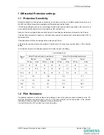
The pilot resistance is used in conjunction with settable padding resistance to achieve the stability biasing of the
relay. The padding resistance must be set in series with the pilot resistance to achieve a standard value. There is
a therefore a maximum value for the pilot resistance for which the padding should be set to zero. The maximum
value of pilot LOOP resistance for the Solkor R mode is 1000
Ω
and for the Solkor Rf mode the maximum LOOP
resistance is 2000
Ω
. When 15kV isolation transformers in the Rf mode the maximum LOOP resistance will be
reduced to 1760
Ω
to compensate for the transformer winding resistance and if the transformer taps are used to
compensate for the effects of pilot capacitance the maximum LOOP resistance is reduced further to values of,
880
Ω
and 440
Ω
depending on the tap used. The actual pilot resistance must be referred through the transformer
at the chosen tap to give an equivalent pilot resistance value to which the padding should be added.
Thus the padding resistance R = (Sv-Rp)/(2T)
Where Rp = Pilot LOOP resistance
Sv = standard value
=1000
Ω
for Solkor R mode (T=1)
=2000
Ω
for 5kV Solkor Rf mode (without transformers) (T=1)
=1760
Ω
for Solkor Rf with 15kV transformers using tap 1 (T=1)
=880
Ω
for Solkor Rf with 15kV transformers using tap 0.5 (T=0.5)
=440
Ω
for Solkor Rf with 15kV transformers using tap 0.25 (T=0.25)
6
Pilot Supervision
Pilot supervision is used to detect failure of the pilot connection. Open circuit Pilots will lead to a loss This is often
applied as standard with the Solkor system but may considered unnecessary at lower voltages or in an
interconnected system where unnecessary tripping of an un-faulted feeder may be tolerated due to limited
consequences in terms of loss of supply and relatively low probability of pilot damaged or failure when compared
to the additional equipment cost.
The Pilot Supervision system uses DC injection which cannot pass through a transformer. For this reason the
Pilot Supervision must be applied at the pilot side of the 15kV isolation transformers if fitted and therefore the
devices must have an isolation level to suit. The Send End unit and B75 Receive End must have 15kV insulation.
The B22 Supervision Relay and B74 Repeat Relay are not connected to the pilots directly and no special isolation
requirements apply to these devices.
7
Overcurrent Guard Relays
Overcurrent Guard relays are connected to the same CTs as the Solkor relay. The output contact is connected in
series with the Solkor Rf such that a Solkor differential operation will not cause a CB trip if the current in the guard
relay (and therefore the local end) is below setting. A separate Solkor contact should be wired an alarm to
indicate that the pilots may be damaged. Care should be taken when applying guard relays that the fault infeed
will be available to operate the guard relay. Application to radial systems may be limited.
Phase fault Guard relays should be set to at least 150% of maximum load current for stability but less than 50% of
the minimum expected phase fault current. These 2 requirements may conflict and a compromise may be
required.
Earth fault guard relays should be set to less than 50% of the minimum earth fault but more than 150% of the
maximum residual expected due to load imbalance. It is important to note that if an electromechanical, variable
setting relay is used as a guard relay, if a low setting is selected the AC burden at rating will be increased. This is
not the case when a modern numerical relay is used as a Guard relay since this will have a fixed burden
independent of the relay setting. The lower burden of the numeric relay may be a major advantage in this
application.
If a numeric Overcurrent guard relay is used, a spare contact from the Solkor can be wired to a binary input of the
Guard relay and used to trigger a waveform record such that the waveform recording for a Solkor operation is
added to the scheme. This function can be extremely useful in identifying the cause of operations caused by pilot
disturbance.
8
Injection Intertripping
Injection intertripping is used to force the remote end circuit breaker to trip for local protection operation. This is
generally started by protection other than the Solkor system since a differential protection system will generally
trip on differential current at both ends regardless of the local current level. Injection Intertripping functions by
injecting AC onto the pilots to simulate a local single end fed fault detection which causes a remote end
©2010 Siemens Protection Devices Limited
Chapter 3 Page 11 of 15


