


Gamma
instabus
Technical product information
June 2014
Gamma arina touch sensor single
double
quadruple
Technical product information
UP 20x, UP 28x/3 and UP 28x/5
Update: http://www.siemens.com/gamma
Subject to change without further notice
Siemens Building Technologies
2.16.1.13/8
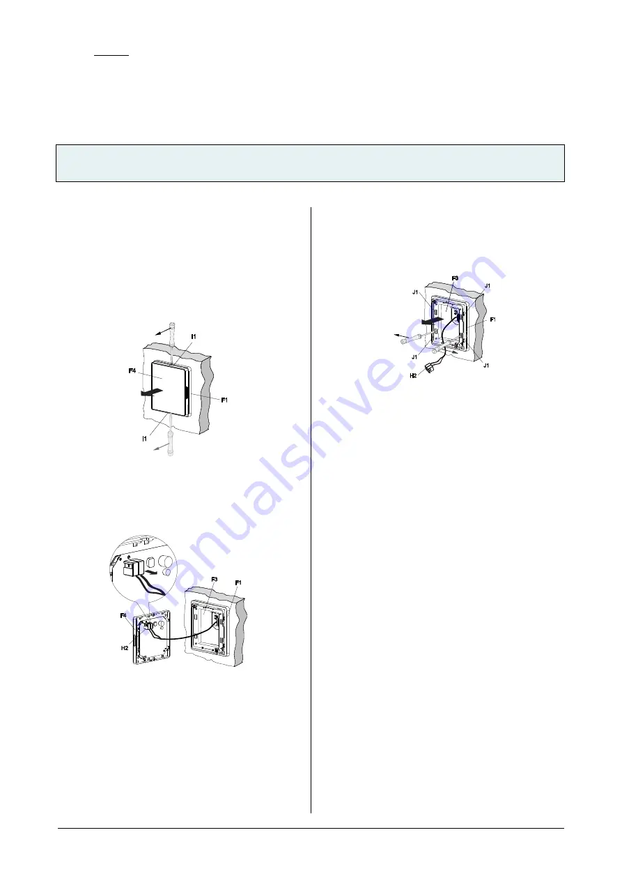
Unmounting
Remove the front housing (F4)
−
Remove the front housing (F4) of the touch sensor
apart from the back housing (behind the front cover
and invisible) with a screw driver, with the back hous-
ing still on the mounting frame (F1)
−
Pull off the KNX connector manually from the front
housing
Figure 7: Remove the front housing
F1
Mounting frame
F4
Front housing
I1
Hole for screwdriver
Figure 8: Remove the KNX connector
F1
Mounting frame
F3
Back housing
F4
Front housing
H2
KNX connector
Remove the back housing (F3)
−
Insert screwdriver to the holes (J1), and press as
showed in Figure 9.
−
Move the back housing out of the mounting frame (F1).
−
Pull the KNX connector (H2) out from the back housing.
Figure 9: Remove the back housing
F1
Mounting frame
F3
Back housing
H2
KNX connector
J1
Hole for screwdriver
Address assignment
−
Press the programming button (F5) on the device to
initiate the assignment of the physical address to the
device (figure 1).
−
The programming LED (E4) turns on to indicate the
programming mode. Upon receiving the physical ad-
dress the device automatically returns to normal oper-
ating mode and the LED turns off. The programming
LED is not invisible when turns off.


