4
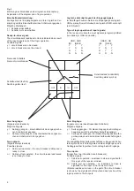
Schaltzustand (sinnbildlich)
Switching state (symbol)
Name des Schalters
Name of circuit-breaker
Zwei Ausgänge:
(Signale stets identisch)
Mögliche Signale:
y =
Seilzug gezogen - Einschaltbarkeit des angesproche-
nen Schalters ist gegeben
n =
Seilzug nicht gezogen - Einschaltbarkeit des angespro-
chenen Schalters ist nicht gegeben
Two outputs:
(Signals always identical)
Possible signals:
y =
Cable pull operated - the circuit-breaker addressed is
ready to close
n =
Cable pull not operated - the circuit-breaker addressed
is not ready to close
Zwei Eingänge:
(Signale von zwei beeinflussenden Schaltern)
Mögliche Signale:
y =
Seilzug gezogen - Für diesen Eingang des Empfänger-
bausteines wird Einschaltbereitschaft signalisiert.
n =
Seilzug nicht gezogen - Für diesen Eingang des Empfän-
gerbausteines wird keine Einschaltbereitschaft signali-
siert.
Die endgültige Einschaltbereitschaft des vorliegenden Schal-
ters ergibt sich durch die Signale an beiden Eingängen und in
Abhängigkeit der logischen Verknüpfung beider Eingänge.
Two inputs:
(Signal from two influential circuit-breakers)
Possible signals:
y =
Cable pull operated - readiness to close is signalled for
this input of the receiver module.
N = Cable pull not operated - no readiness to close is
signalled for this input of the receiver module.
Ultimate readiness to close on the part of the circuit-breaker
is shown by the signals at both inputs and as a function of the
logic operation of both inputs.
Schaltzustand (textlich)
Switching state (text)
IN
IN
OUT
OUT
Einschaltbarkeitsmeldung:
Als Ergebnis der Eingangssignale und ihrer logischen Ver-
knüpfung wird die Einschaltbarkeit des Schalters angegeben.
Mögliche Meldungen:
y = Schalter einschaltbar
n = Schalter nicht einschaltbar
Ready-to-close signal:
The circuit-breaker's readiness to close is indicated as a result
of the input signals and of their logic operation.
Possible signals:
y = circuit-breaker can be closed
n = circuit-breaker cannot be closed
Logische Verknüpfungsart der Eingangssignale:
Im Empfängerbaustein werden die Eingangssignale logisch-
UND-verknüpft (zwei Schieber) bzw. logisch-ODER-verknüpft
(ein Schieber).
Type of logic operation of input signals:
In the receiver module the input signals are logically ANDed
(two slides) or ORed (one slide).
UND - AND
IN1
IN2CB
Y
Y
Y
Y
N
N
N
Y
N
N
N
N
ODER - OR
IN1
IN2CB
Y
Y
Y
Y
N
Y
N
Y
Y
N
N
N
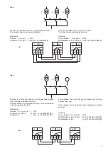
Erklärung des Sinnbildes und der logischen Verknüpfung
Explanation of the diagram and of logic operation
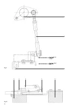
Fig. 3


