Description of the individual safety relays
3.6 3TK28 safety relays with relay enabling circuits
3TK28 safety relays
Manual, 07/2016, NEB926157502000/RS-AB/003
55
3.6.4
3TK2821 / 3TK2824 safety relays
3.6.4.1
Applications
Applications of the 3TK2821/24 safety relay
You can use the 3TK2821/24 safety relays in EMERGENCY STOP devices according to
DIN EN / IEC 60947-5-5 and in safety circuits according to DIN EN / IEC 60204-1, as a basic
unit or contact extension.
With the device, a maximum performance level PL
e
/Cat. 4 in accordance with
DIN EN ISO 13849-1 or SILCL 3 in accordance with DIN EN/IEC 62061 can be achieved.
Depending on the hazard assessment, additional measures may be necessary in the sensor
circuit (e.g. protected cable installation). If the 3TK2821/24 is used as a contact extension,
the achievable PL / Cat. / SIL is equivalent to that of the basic unit.
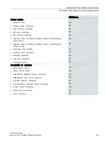
Table 3- 1
Achievable SIL CL/PL/Cat. in applications
1-channel
2-channel
Contact extension
SIL (DIN EN / IEC 61508)
1
1 (2)*
3
PL (DIN EN ISO 13849)
c
c (d)*
e
Cat. (DIN EN ISO 13849)
1
1
4
* PL d or Cat 4 can only be achieved if faults can be ruled out for the positive opening
contacts (to IEC 60947-5-1 Annex K) and for the mechanical system. In the sensor circuit,
DC = 0.
3.6.4.2
Description of function and connection information
The 3TK2821 safety relay has three enabling circuits (safe circuits) as NO circuits and a
signaling circuit as an NC circuit.
The 3TK2824 safety relay has two enabling circuits (safe circuits) as NO circuits.
The number of enabling circuits can be increased by adding one or more 3TK2830
expansion blocks.
The operating state and functioning are indicated by three LEDs.
When the EMERGENCY STOP buttons or limit switches are released and the ON button is
pressed, the internal circuit of the safety relay and the external contactors are monitored to
ensure that they are functioning correctly.
Connect the EMERGENCY STOP button or the limit switch in the supply cable between A1
and +24 V or in the supply cable of the A1 terminal (L/+24 V DC). If evaluation is to take
place via two channels, then connect channel 2 between A2 and 0 V or N. Connect the ON
button in series with the NC contacts of the external contactors (feedback circuit) to the
terminals Y1, Y2.

