17
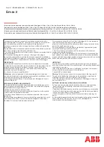
Figure 9: Manual opening mechanism components
Item
Description
Item
Description
60.0
Mechanism housing
102.3
Interlock lever
101.0
Magnetic actuator
114.0
Lockout switch
102.1
Manual opening shaft
60.0
60.0
101.0
101.0
Figure 10: Use of manual opening
lever
Detail A
Detail B
101.3
102.1
114.0
102.3
101.3
102.1
114.0
102.3
Manual opening
The manual opening lever can be used to
open the circuit breaker manually, and can
also be used to block the circuit breaker in the
OPEN position. The manual opening lever is
located to the right side of the operator, on
the exterior of the type SDV7-MA circuit
breaker enclosure.
Figure 9 shows the mechanism internal
components that are part of the manual
opening system. In detail A, the interlock
lever (102.3) is shown in the normal position.
The shaft (102.1) of the manual opening
lever is connected by a spring to the interlock
lever (102.3). When the manual opening
lever is rotated a few degrees, electrical
opening is disabled by position switch S6
(114.0). On further shaft rotation, the circuit
breaker opens.
If the shaft is returned to the normal position,
electrical closing and opening operations can
be performed. If instead, the manual opening
shaft is rotated 90°, the interlock lever
(102.3) prevents closing by mechanically
blocking movement of the magnetic actuator.
In this position, position switch S6 (114.0)
continues to disable electrical operation.
When maintenance is to be performed,
operation of the circuit breaker can be
prevented by installing a padlock on the
external manual opening lever. Refer to
Figure 10: Use of manual opening lever.