background image

22

6146

2

2019

-

SH 360

Control Panel Installation 

EN

Find a suitable location for the control panel where it does not obstruct or is obstructed by other devices. Install the control panel on a fl at surface where 

it is easy to use. 

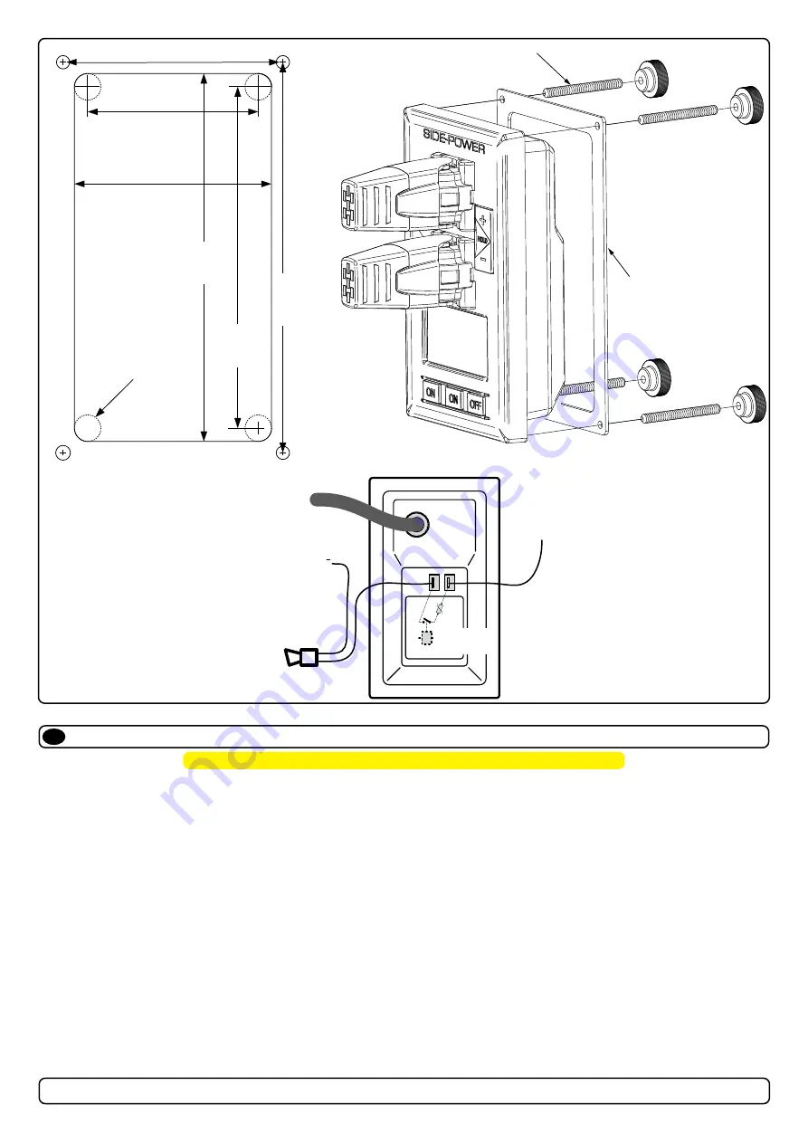
1.  Use the supplied cut-out template to mark the area to remove on your control dash. 

2.  Cut out the area per template for the control panel. (

NB: If the front surface around your cut out is jagged or chipped, use a sealant

to assist the gasket.)

3.  Place the gasket to the back face of the panel 

4.  Plug cables into the connectors at the rear of the control panel. 

5.  Insert the control panel in place and fasten screws.

6.  Insert the control panels covering caps.

MC_0042

!

 Please refer to the graphic for special considerations relating to your model 

!

MG_0063

GASKET   

4x SCREWS 

58 mm

67 mm

125 mm

116 mm

132.7 mm

75.7 mm

Ø 4.5 mm

Ø 4.5 mm

Ø 4.5 mm

Ø 4.5 mm

(S-link)

External alarm buzzer

12V / 24V DC - max 0,5A

External alarm / buzzer connection

Supply

+ 12V / 24V DC 

-

+

Ø 4.5 mm

Rear

side

of pa

nel

Internal

fuse / relay

Summary of Contents for SH-300

Page 1: ...Made in Norway Sleipner Motor AS 2020 SLEIPNER MOTOR AS P O Box 519 N 1612 Fredrikstad Norway www side power com Document id Revision Date 6146 2 Installation manual 2019 SH 360 300 ...

Page 2: ...tions 5 Technical Specifications 5 Positioning of the tunnel thruster 6 Tunnel Length 7 Tunnel Installation in Sailboats 8 Water Deflection 9 Tunnel ends 10 Tunnel Installation 11 12 Stern Tunnel Installation 13 Thruster installation Hydraulic Thruster Installation Considerations and Precautions 14 Technical Specifications 15 Technical Requirements Hydraulic hose connections to motor 16 Gear Leg M...

Page 3: ...ank to change filters fill oil and inspect gauges and indicators It is the installers responsibility When installing Side Power equipment to follow the outlined regulations classification rules electrical mechanical according to international or special national regulations Instructions in this guide cannot be guaranteed to comply with global electric mechanic regulations classification rules It i...

Page 4: ..._0214 Thruster Measurements EN Measurement code Measurement description mm inch ID Internal tunnel diameter 300 11 81 H Motor Height 356 14 02 W Width 258 10 16 L Length 258 10 16 WD Water Depth 450 17 72 TL Minimum tunnel length 370 14 57 TL recommended Recommended tunnel length 550 21 65 T min Minimum tunnel wall thickness 10 0 39 T max Maximum tunnel wall thickness 360 ...

Page 5: ...ted from the motor Tunnel Cross spun with rowing G R P tunnel Steel aluminium tunnels available at request Propeller SH 100 SH 160 SH 240 SH 320 SH 360 5 blade skewback Q prop propeller fibreglass reinforced composite SH 420 SH 550 Symmetrical 4 blade kaplan propeller fibreglass reinforced composite Safety Flexible coupling between hydraulic motor and driveshaft protects gearsystem if propeller ja...

Page 6: ...s deep as possible under the waterline 2 Deeper installations prevent air from being sucked into the tunnel from the surface resulting in reduced thrust performance and increase noise levels during operation Deeper installations increase water pressure for maximum efficiency from the thruster The centre of the tunnel should be a minimum of 1 x the tunnel diameter below the waterline The installer mu...

Page 7: ...bottom tunnel lengths are respectable lengths from one another 2 If the tunnel is too long the friction inside will reduce the water speed and thereby the thrust 3 If the tunnel is too short typically only in the bottom section of the tunnel cavitation problems can occur as water flow will not be able to straighten itself before reaching the propeller This cavitation will reduce performance and in...

Page 8: ...it the tunnel halfway into the underneath section of the existing hull Strengthen it with a deflector spoiler directing the water flow around the tunnel This will allow installation of the thruster in the proper position on the boat maintaining the reliability and space advantages of the tunnel thruster This installation is being used by some of the world s largest sailboat builders and has proven...

Page 9: ...gled slightly down because of the water flow on this area 2 3 Making a deflector spoiler in front and underneath the tunnel can also reduce damage to the thruster and drag The deflector spoiler will push the water flow out from the hull so water can pass by the back face of the tunnel The shape and size of this deflector spoiler will depend on the hull shape The easiest way of making the deflector...

Page 10: ...hereby reduces the effective tunnel diameter and thrust The turbulence cavitation hits the propeller and will lessen the propellers performance and create excess noise 2 For steel aluminium hulls angled tunnel ends also offer similar performance as a rounded connection 3 A rounded tunnel end makes the thruster draw water from along the hull side creating a vacuum that will suck the boat sideways and...

Page 11: ...over the back face 5 Cut the tunnel ends to the desired shape and lightly sand its surface and clean with acetone or similar where you are going to apply fibreglass NB Do not cast fibreglass on the area were the thruster will be placed 6 Cast the tunnel to the inside of the hull use at least eight layers of 300g fibreglass and resin preferably alternating mat and rowing types of fibreglass To round...

Page 12: ...unnel installed and cast 1 Round the edges with a radius of 10 of the tunnel diameter 2 For steel aluminium hulls make a slope with a length of 10 15 of the tunnel diameter NB If this is not possible round the tunnel end as much as possible 3 Additionally cast two layers on the outside of the tunnel hull in a 10cm area 4 Follow the same method if making the deflector spoiler You must apply gel coa...

Page 13: ...019 SH 360 Stern Tunnel Installation EN Stern thruster installation has extra considerations and precautions and thruster installation procedures See the attached manual supplied in the stern thruster kit MC_0003 ...

Page 14: ... system is NOT installed please ensure the following Install an oil filter to keep the oil clean Fit an oil cooler or use an oil tank to ensure the maximum oil temperature is 43 50 degrees Celcius Hydraulic thrusters are supplied with hydraulic motors only The installed hydraulic system is the responsibility of the fitter installer and must be within the limitations outlined in this manual to ensu...

Page 15: ... 287 USG PSI 8 93 2494 10 30 3335 11 52 4162 U19 L min Bar 41 0 144 47 3 193 52 9 241 USG PSI 10 83 2088 12 50 2799 13 98 3495 BA19 L min Bar 40 1 145 46 3 194 51 8 242 USG PSI 10 59 2103 11 44 2813 13 69 3509 U23 L min Bar 49 4 121 57 162 63 8 202 USG PSI 13 05 1755 15 06 2349 16 86 2929 SH360 U19 L min Bar 46 5 177 53 7 236 55 2485 USG PSI 12 3 2567 14 17 3423 14 53 35975 BA19 L min Bar 45 3 176...

Page 16: ...on varies Motor type Port A B Port flange threads Drain port U6 1 2 BSP 1 4 BSP U8 1 2 BSP 1 4 BSP U10 3 4 BSP 1 4 BSP U11 3 4 BSP 1 4 BSP U14 3 4 BSP 1 4 BSP U16 3 4 BSP 1 4 BSP U19 3 4 BSP 1 4 BSP U26 3 4 BSP 1 4 BSP U29 3 4 BSP 1 4 BSP U33 3 4 BSP 1 4 BSP U37 3 4 BSP 1 4 BSP U37 3 4 BSP 1 4 BSP U50 1 BSP 1 4 BSP P42 1 3000 PSI SAE J518 ISO 6162 Code 61 3 8 16 UNC 2B 22 deep 1 4 BSP P52 1 1 2 300...

Page 17: ... on the gear leg to ensure it is centred and rotates freely with the same clearance from each blade to the tunnel wall Place top motor bracket to measure the driveshaft has come through the motor bracket at the correct height Remove the gear leg and propeller for final installation 6 Apply appropriate sealant to both sides of the gasket and place on the gear leg Place the gear leg in the tunnel wi...

Page 18: ...e propeller and tighten the anode holding screw Apply a thread glue Loctite 243 or similar to ensure that the anode holding screw does not un screw itself from during the rotation of the propeller 4 Apply antifouling to the gear leg and propeller Do not apply antifouling to any rubber elements of the gear leg or anodes MG_0033 DRIVE PIN PROPELLER WASHER LOCK NUT ANODE ANODE HOLDING SCREW Apply Loc...

Page 19: ... is required the propeller can rotate via hand power NB Rotating the propellers can be hard because of the gear reduction and the motor 9 Ensure to install the drain hose Apply the gear leg and propeller with antifouling designed for propellers Do not apply to the propeller drive shaft the anodes or the end of the gear leg facing the propellers Only in shallow installations in workboat and fishing...

Page 20: ... feed nipple on the motor bracket Fasten the two tube clamp screws NB Ensure the oil tube has no loops and forms an airlock to stop the oil flow Ensure the oil tube angle is sufficient to allow oil to flow freely into the gear leg 3 Fill the oil tank with the same gear oil used in the gear leg The oil tank works as an indicator to ensure there is oil in the gear leg at all times NB Fill and drain the ...

Page 21: ...short as practically possible POWER Cable Must be one in each system length 2 5m 4 Port T Connector The 4 port T connector allows multiple spur cables to be connected NB Comes with two sealing caps to protect T Connector Must be one for each spur including power cable BACKBONE extender Connects two BACKBONE cables to extend length END terminator Must be one for each end of the BACKBONE loop Power ...

Page 22: ...ut is jagged or chipped use a sealant to assist the gasket 3 Place the gasket to the back face of the panel 4 Plug cables into the connectors at the rear of the control panel 5 Insert the control panel in place and fasten screws 6 Insert the control panels covering caps MC_0042 Please refer to the graphic for special considerations relating to your model MG_0063 GASKET 4x SCREWS 58 mm 67 mm 125 mm...

Page 23: ...nd filled with gearoil Correct drive direction as per controlpanel The bolts holding the gearhouse and motorbracket together are tightened correctly The bolts holding the motor to its bracket are tightened correctly The thruster has been installed as per the instructions in this manual and all points in checklist above have been controlled Signed Date Extra pre delivery tests by installer yard who...

Page 24: ...uipment supplier that the installation instructions of the Installation and Operation Manual have been complied with and that the defect remains e warranty service shall be performed only by the Warrantor or an authorized Service Centre and any attempt to remedy the defect by anyone else shall render this warranty void 5 There shall be no warranty for defects or damages caused by faulty installati...

Page 25: ...25 6146 2 2019 SH 360 MC_0037 Notes EN ...

Page 26: ...26 6146 2 2019 SH 360 MC_0037 Notes EN ...

Page 27: ...27 6146 2 2019 SH 360 MC_0037 Notes EN ...

Page 28: ...ocument was correct at the time it was published However Sleipner Motor AS can not accept liability for any inaccuracies or omissions it may contain Continuous product improvement may change the product specifications without notice Therefore Sleipner Motor AS can not accept liability for any possi ble differences between product and document ...

Reviews: