background image

FAULT DIAGNOSIS   


47 

8025816/V1-0/2020-07-06|SICK 

Subject to change without notice 

OP ERA T ING  INS T RU C T IO NS   | VMS4400 Contour Verification 

8.2


Fault indications of the components 

8.2.1


Fault indication on the LMS4x21 


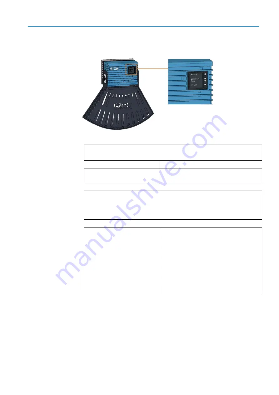
Fig. 30:  Status  indicators on the LMS4x21 


Fault indication 
The Status LED does not light up. 

Fault cause 

Possible solution to the problem 

Fuse is defective. 


Check the fuse block in the cabinet and, 
if necessary, replace the defective fuse. 


Fault indication 
The Status LED lights up red.  
The 2D LiDAR sensor independently monitors beam generation and automatically shuts 
it down in the event of irregularities. The sensor no longer sends any measured values. 

Fault cause 

Remedy 


Error during initialization or 
self-test. 


LMS4x21 is not in measuring 
mode or is in measuring mode, 
but errors have occurred. 


Check the voltage supply. 


Interrupt the voltage supply to the LMS4x21. 


Restore the voltage supply.  

 
If the fault persists or occurs again after 
the voltage supply has been restored: 


Check the device status using SOPAS 
(see below).  


If errors are listed there, contact SICK Service. 

Tab. 4:  Fault indication on the 2D  LiDAR sensor 


Summary of Contents for VMS4400 CV

Page 1: ...OPE RAT I NG I NST RUCT IO NS VMS4400 Contour Verification Track and trace systems...

Page 2: ...ed bycopyright The associated rightsare reserved bySICKAG Reproductionof this document orparts of this document is only permissible within the limits of the legal provisions of copyright law Anymodifi...

Page 3: ...very 11 3 2 System components 12 3 2 1 LMS4x21 2D LiDAR sensors 13 3 2 2 Trigger photoelectric sensor 14 3 2 3 Incremental encoder 15 3 2 4 Cabinet 16 3 3 Operating principle 18 3 3 1 Automated operat...

Page 4: ...ing the power supply unit 42 7 2 6 Replacing the photoelectric retro reflective sensor 44 7 2 7 Replacing the incremental encoder components 45 8 Fault diagnosis 46 8 1 Response to errors 46 8 2 Fault...

Page 5: ...o account when assemblingthe data and information contained in this document The manufactureraccepts no liabilityfordamage caused by Failure to observe this document Non compliancewith notes and regul...

Page 6: ...5 Other relevant technical documentation information Technical system documentation Technical data Connectiondiagram Terminal diagram Operatinginstructions forthe followingsystemcomponents OperatingIn...

Page 7: ...em ensures compatibilitywith existingsolutions from SICKand enables adaptations to customer specific applications such as identification systems ordynamic scales Theyenable full status control thereby...

Page 8: ...aneye is not at risk whenbrieflyexposed to the radiationforup to 0 25 seconds Exposure to the laser beam forlongerperiods of time maycause damage to the retina The laserradiationis harmlessto humanski...

Page 9: ...lications in large industrial plants accordingto Article 2 4 e RoHS2011 65 EU and must therefore onlybe used in such plants The product is neithersuitable norapproved for use outsideof these plants SI...

Page 10: ...nents Warninglabels must not be removed orcoveredup If labels are missing these must be affixed Damaged labels must be replaced Symbol Meaning Hazardous point warning Hazardous electrical voltage warn...

Page 11: ...heck that the deliveryincludes all components listed onthe deliverynote Systemcomponents Cabinet with system controller dimensioningcontroller powersupplymodule and Ethernet switch FourLMS4x21 2DLiDAR...

Page 12: ...components Fig 1 Components of the VMS4400 CV Legend 1 2D LiDAR sensors 2 Photoelectric retro reflective sensor optional 3 Incremental encoder optional 4 Cabinet with system controller dimensioningcon...

Page 13: ...o 2D LiDAR sensors are mounted belowthe conveyorbelt The laserscannerbeam is guided through the seam betweentwo conveyorbelts They detect the bottom as well as the right and left side of the object Tw...

Page 14: ...ed back bya reflector Senderand receiverare arranged parallel to one anotherin the housingof the photoelectric retro reflective sensor If the light beam is interrupted byanobject a switchingsignal is...

Page 15: ...l and pivot range of the springarm compensates forunevenness on measurement surface Measurement of linearmovements Detectionof positionand speed directlyonthe runningsurface of the conveyorusing a pre...

Page 16: ...rminals formainsvoltage IN 230VAC 50 Hz 3 System controller examplein the image SIM2000 4 Powersupplyunits 5 Terminals 24 V DC and fuse module OUT 6 RCD residual current device forprotective contact p...

Page 17: ...e distance data of the 2DLiDAR sensors and based onthis data determines whether or not any deformationis present The measurement results are transmitted to the system controllervia CAN bus The system...

Page 18: ...t Legend 1 Rotational angle of the objects onthe conveyorbelt up to 45 2 Required minimumdistance max object height The VMS4400 CV detects singulated cuboidobjects onflat conveyingsystems such as conv...

Page 19: ...otice OPERATING INS TRU C TIONS VMS4400 Contour Verification Fig 7 No touching no side by side Legend 1 The objects must not be located side by side 2 The objects must not be touching Otherwise the tr...

Page 20: ...t span a two dimensional measuringrange and performa non contact scanof the surface of the object onthe conveyingequipment The 2D LiDAR sensors transmit the acquired measurement points to the dimensio...

Page 21: ...recorded contourand the ideal contourof the enclosingcuboid determines the extent of the deformation The VMS4400 CV does not differentiate betweendents and bulges The change in dimensionbased onthe vo...

Page 22: ...first zone zone 2 reaches fromthe upperedge of the conveyorbelt to the maximum object height A qualityparametercanbe set separatelyforboth zones and the sensitivityof the deformationcontrol canbe dete...

Page 23: ...lerreceives the measurement results fromthe deformation checkof the dimensioningcontrollerand assigns the calculated measurement and deformation results to the relevant object From here the data are s...

Page 24: ...n of both in anydesired arrangement Allows automated object identificationusingbarcodes Streamlines processautomation The weighingstation consists of a dynamic scale It determine the weight of the pas...

Page 25: ...s will leadto problems ora reductionin measurement accuracy 3 4 1 Requirements onthe ambientconditions The operationsite of the VMS4400CV must have the followingfeatures Closed orcovered room Flat and...

Page 26: ...maybe installed in the vicinityof the measuring station NOTE Any relative movement of anobject onthe conveyingequipment will result in distorted measurement results If the objects rotate vibrate roll...

Page 27: ...e conveying equipment in such a waythat it is free of vibrations and oscillations The smallest permissible distanceof the measuringobject from the zeropoint of the 2D LiDAR sensors is 900 mm The zero...

Page 28: ...and experience as well as knowledge of the relevant regulations and standards to be able to perform work assigned to them and to identifyand avoid anypotential dangers independently Electricians have...

Page 29: ...avoid anypotential dangers independently DANGER HAZARDOUSELECTRICALVOLTAGE Touchinglive devices which maystill be energized canlead to death burns or electrical shock Electrical work mayonlybe perform...

Page 30: ...DAR sensor master 3a CAN bus 3b Ethernet 3c Synchronization 4 2D LiDAR sensor slave 4a Ethernet 4b Synchronization 5 Cabinet 5a Feed 100 264 V AC 50 60 Hz 6 Dimensioning controller e g APU8520 6a CAN...

Page 31: ...oningof the track and trace system is carried out by the manufacturer All of the system functions are set up byconfiguringthe measuring conditions on site NOTE Initial commissioningbythe manufactureri...

Page 32: ...ro reflective sensor Cleaningthe light emissionand reflector Visuallyinspect the object detectionphotoelectric sensorand reflectorforrotationthat mayhave occurred as a result of touchingor the like 4x...

Page 33: ...ct the entire reference object whenit passes the laserline Use adhesive tape to attach a maximumof one defective object as the reference object Make sure that the reference object does not change its...

Page 34: ...xposed to the radiationforup to 0 25 seconds Exposure to the laserbeam forlongerperiods of time maycause damage to the retina The laserradiationis harmlessto humanskin Neverlook directlyinto the laser...

Page 35: ...reflectorare aligned correctlyat regular intervals 7 1 5 Checking the incrementalencodercomponents The measuringwheel of the incremental encodermust havedirect and steadycontact with the conveyorbelt...

Page 36: ...forcleaning Only knock the dirt off the ventilationgrilles orcleanthem with a brush Neverwet clean the grilles Fig 20 Replacing the filters at the air inlets and outlets of the cabinet Regularlycheck...

Page 37: ...ing commissioningormaintenancework suitable eye protectionmust be worn Avoid laserbeam reflections caused by reflectivesurfaces Inparticularduring mountingand alignment work Do not openthe housing Cur...

Page 38: ...2 Dowel pins and locating holes Pressthe device into place with one hand and screw the device to the mountingplate Make sure that the device is securelyscrewed on Screw the connectingcables back on Sw...

Page 39: ...xample Unscrew the fixingscrew forthe system controller Remove the system controllerfromthe cabinet Fig 24 Removing the microSD card from the system controller MSC800 in this example Remove the microS...

Page 40: ...s example The batterymust be replaced whendrained Fig 25 Location of the battery in the system controller MSC800 in this example Remove the black plasticcoveronthe system controller Remove the battery...

Page 41: ...remove all connectingcables fromthe device Usinga magnetized flat blade screwdriverora torx screwdriver undo the fourscrews onthe bracket of the dimensioningcontroller NOTE Hold the device with one h...

Page 42: ...work on the cabinet Before workingonelectrical components observe the five safetyrules Disconnect Secure against beingswitched back on Ensure that there is no voltage Ground and short circuit Coverore...

Page 43: ...clip onthe rearwall backwards Lift the powersupplyunit and pull it forward and out of the bracket Place the new powersupplymodule onthe mountingrail of the cabinet and press backwards until the power...

Page 44: ...Unscrew the hexagonscrews NOTE Hold the photoelectric retro reflective sensorfirmlywith one hand duringthe procedure Remove the defective photoelectric sensorfrom the mountingbracket Screw the replace...

Page 45: ...onents Unscrew the M12 plugconnectorfrom the male connectoronthe incremental encoder Loosenand remove the fixingscrews Fig 29 Replacing the incremental encoder Mount the replacement device onthe conve...

Page 46: ...ANGERIN THE EVENT OF MALFUNCTION Cease operationif the cause of the malfunctionof the track and trace system has not beenclearlyidentified Take the track and trace system out of operation if the fault...

Page 47: ...indication The Status LEDlights up red The 2D LiDAR sensorindependentlymonitors beamgenerationand automaticallyshuts it downin the event of irregularities The sensorno longersends anymeasured values...

Page 48: ...LEDshould light up onthe system controller This means that the system controllerhas received a positiveresponse from all of the components and that the devices are communicatingwith one another Fault...

Page 49: ...it or check the application conditions Fault indication LED receive indicatoris flashing Fault cause Possible solutionto the problem Reflectoris beingdetected in the fringe range Readjust the photoele...

Page 50: ...the triggering on the system controller MSC800 in this example If the LED does not light up possible causes might be Cause Remedy Beam path is permanently interrupted byanobject Eliminate the permane...

Page 51: ...e incremental signals on the system controller MSC800 in this example If the LEDs do not flash possible causes might be Cause Remedy There is no insufficient contact betweenthe measuringwheel and the...

Page 52: ...ncyfordata output 1 s Min detectable defect 10 mm relative to enclosingcuboid and 500 mm2 Holes cannot be detected Conveyorspeed Up to 2 0 m s 1 Synchronous and consistent belt speed in the measuringr...

Page 53: ...accordance with international directives and regulations batteries accumulators and electrical orelectronic devices must not be disposed of with household waste The owneris obligated to dispose of th...

Page 54: ...support sick jp Malaysia Phone 603 8080 7425 E Mail enquiry my sick com Mexico Phone 52 472 748 9451 E Mail mario garcia sick com Netherlands Phone 31 0 30 229 25 44 E Mail info sick nl New Zealand Ph...

Reviews: