background image

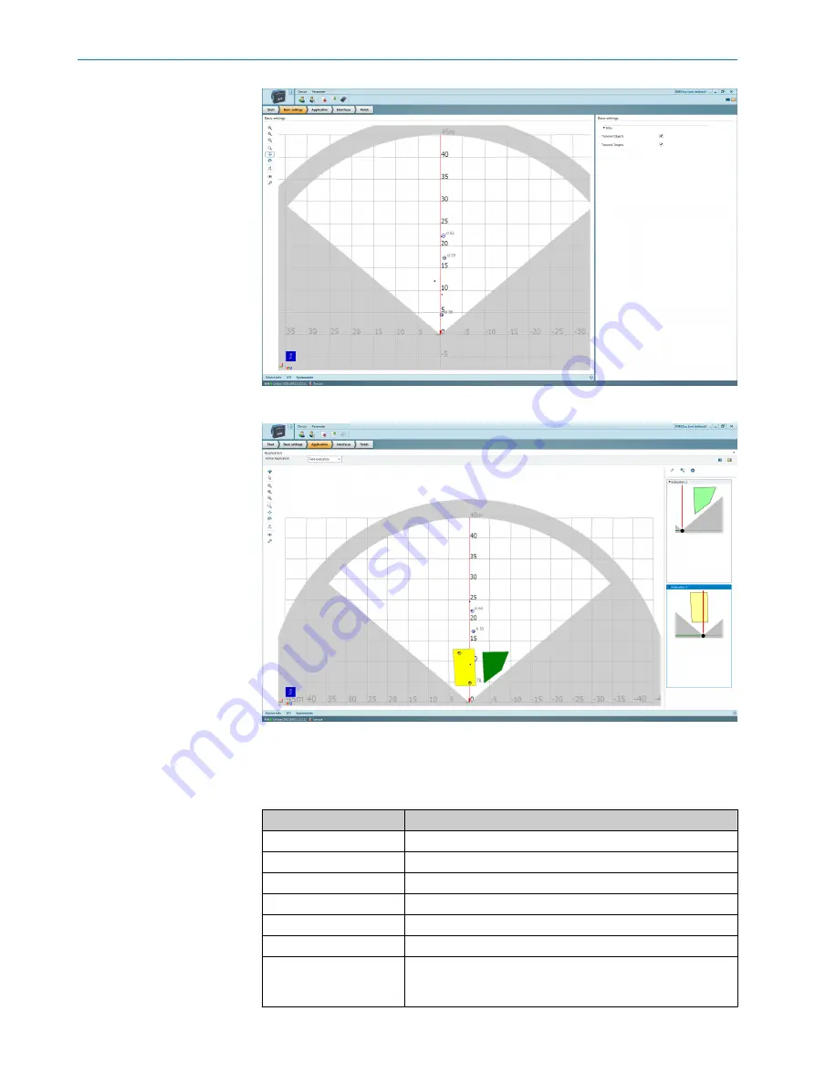
Application

 (field evaluation): Scan display for adapting the field geometry (left-hand

side) and entering detection parameters (right-hand side):

The 

Edit field points

 tool (mouse pointer in the list of tools to the left of the scan

view) can be used to customize the field geometry with the assistance of the
mouse pointer. Alternatively, the field vertices can also be customized by entering
the coordinate values in the 

Field coordinates

 mask.

Table 5: Options for editing the field geometry with the mouse pointer

Function

Procedure

Scale field

Drag square red handle.

Rotate field

Drag round black handle.

Customize field shape

Drag square green handle.

Add field vertices

Double-click in required position.

Delete field vertices

Click to select square green handle and press the 

[del]

 key.

Delete field

Press the 

[del]

 key without first selecting a green handle.

Insert new field (function
is only available if a field
has not been created)

Select the 

Insert field points

 tool, click to set field vertices, and

double-click last field vertex to close the field.

OPERATION

20

O P E R A T I N G   I N S T R U C T I O N S | RMS3xx

8021530/19JS/2021-02-09 | SICK

Subject to change without notice

Summary of Contents for RMS3 Series

Page 1: ...O P E R A T I N G I N S T R U C T I O N S RMS3xx Radar sensors...

Page 2: ...ble within the limits of the legal determination of Copyright Law Any modi fication abridgment or translation of this document is prohibited without the express written permission of SICK AG The trade...

Page 3: ...12 4 1 Transport 12 4 2 Unpacking 12 4 3 Transport inspection 12 4 4 Storage 12 5 Mounting 14 5 1 Mounting instructions 14 6 Electrical installation 15 6 1 Wiring instructions 15 6 2 Connection diagr...

Page 4: ...chanics electronics 27 10 5 Ambient data 28 11 Accessories 29 12 Annex 30 12 1 EU declaration of conformity Certificates 30 12 2 Licenses 30 12 3 Cybersecurity 30 CONTENTS 4 O P E R A T I N G I N S T...

Page 5: ...n on operating the machine or system in which the device is integrated For more information refer to the operating instructions of the specific machine or system 1 2 Explanation of symbols Warnings an...

Page 6: ...its intended purpose and is not described in this documentation Health hazards as a result of high frequency electromagnetic radiation The RMS3xx radar sensor is designed for operation in accordance...

Page 7: ...ories With special variants where optional extras have been ordered or owing to the latest technical changes the actual scope of delivery may vary from the features and illustra tions shown here 2 4 M...

Page 8: ...ices in their particular application Commissioning configura tion Basic knowledge of the computer operating system used Basic knowledge of the design and setup of the described connections and interfa...

Page 9: ...e housing Electrical voltage can cause severe injury or death Work on electrical systems must only be performed by qualified electricians Follow the notes in the operating instructions Install the gro...

Page 10: ...inted safety notes multilin gual Brief information and general safety notes Components not contained in the delivery Component Comment SOPAS_ET configuration software Available online at www sick com...

Page 11: ...ect detection Link No connection O green Ethernet connection green Data transmission via Ethernet con nection O yellow CAN connection yellow Data transmission via CAN connec tion illuminated flashing...

Page 12: ...attaching the connecting cable 4 3 Transport inspection Immediately upon receipt in Goods in check the delivery for completeness and for any damage that may have occurred in transit In the case of tra...

Page 13: ...rage periods of longer than 3 months check the general condition of all components and packaging on a regular basis TRANSPORT AND STORAGE 4 8021530 19JS 2021 02 09 SICK O P E R A T I N G I N S T R U C...

Page 14: ...f the device It should be mounted so that it is exposed to as little shock and vibration as possi ble Optional mounting accessories are available see Accessories page 29 Use of a weather hood and a mo...

Page 15: ...e technical data see Technical data page 26 Configure the circuits connected to the device as ES1 circuits or as SELV circuits SELV Safety Extra Low Voltage The voltage source must meet the requiremen...

Page 16: ...connector Pin Short form Signal description M12 male con nector 5 pin A coded 1 4 3 5 2 1 L Supply voltage 9 5 36 V DC 2 IN1 Input 1 3 GND Earth 4 OUT1 Output 1 5 GND IN1 2 Earth input 1 2 6 3 Connec...

Page 17: ...cording to the connection diagram Connection diagram page 15 3 2 1 Figure 4 RMS3xx connection overview 1 Ethernet 2 CAN I O 3 Power 3 Switch on the supply voltage The initialization phase starts the P...

Page 18: ...the connection can be established via a USB connection using an Ethernet USB adapter NOTE The current version of the SOPAS ET software can be downloaded from www sick com SOPAS_ET The respective syste...

Page 19: ...ice window features various views supporting a selection of functions Available views and functions Start Start device configuration with display of information about the device left hand side and dis...

Page 20: ...with the mouse pointer Function Procedure Scale field Drag square red handle Rotate field Drag round black handle Customize field shape Drag square green handle Add field vertices Double click in requ...

Page 21: ...parameters that are made in SOPAS ET are not saved automatically in the device After you have completed the configuration you must save it in the device permanently by pressing the Save permanent butt...

Page 22: ...egrams can be found in the Technical Information Telegram Listing RMS3xx publication English no 8021531 7 OPERATION 22 O P E R A T I N G I N S T R U C T I O N S RMS3xx 8021530 19JS 2021 02 09 SICK Sub...

Page 23: ...nditions and climate Specialist Clean housing Depends on ambient conditions and climate Recommended Every 3 months Specialist Check the screw connections and plug connectors Depends on the place of us...

Page 24: ...g signals are output via the I O inter face No detection signals present Device configuration faulty Bad connection Check alignment of the detec tion area device configuration and connections No data...

Page 25: ...o the environment due to improper disposal of the device Disposing of devices improperly may cause damage to the environment Therefore observe the following information Always observe the national reg...

Page 26: ...o detection possible at 1 m 2 Typical radar cross section value for a pedestrian 3 Typical radar cross section value for a car Working range diagram 6 5 vertical 16 2 horizontal 100 3 Distance in m fe...

Page 27: ...t protected temperature protected 10 4 Mechanics electronics Connection type 1 x M12 male connector 8 pin A coded 1 x M12 male connector 5 pin A coded 1 x M12 female connector 4 pin D coded Supply vol...

Page 28: ...agnetic compati bility EMC ETSI EN 301 489 1 ETSI EN 301 489 3 EN 61000 6 2 Vibration resistance EN 60068 2 6 2008 02 Shock resistance EN 60068 2 27 2009 05 Ambient operating temper ature 40 C 65 C St...

Page 29: ...essories and where applicable mounting information can be found online at www sick com RMS3xx ACCESSORIES 11 8021530 19JS 2021 02 09 SICK O P E R A T I N G I N S T R U C T I O N S RMS3xx 29 Subject to...

Page 30: ...ility of the program for a particular purpose More details can be found in the GNU General Public License View the complete license texts here www sick com licensetexts Printed copies of the license t...

Page 31: ...ANNEX 12 8021530 19JS 2021 02 09 SICK O P E R A T I N G I N S T R U C T I O N S RMS3xx 31 Subject to change without notice...

Page 32: ...080 7425 E Mail enquiry my sick com Mexico Phone 52 472 748 9451 E Mail mexico sick com Netherlands Phone 31 0 30 229 25 44 E Mail info sick nl New Zealand Phone 64 9 415 0459 0800 222 278 tollfree E...

Reviews: