


8014640/ZMG2/2017-05-12
• Subject to change without notice • SICK AG • Waldkirch • Germany • www.sick.com
3
LeCtor62x | SICK
Step 3: Configuration
a. Configuration without PC
You can set the read properties of the device directly
on the device using the two function buttons.
1. Start “edit” mode.
3 sec
Ready
Read Diagn
Result
TeachIn
LED
Auto-Setup
Data
Autofocus
LNK TX
Userdefined
300
200
100
70
40
100
0
[mm]
[%]
Ready
Read Diagn
Result
TeachIn
LED
Auto-Setup
Data
Autofocus
LNK TX
Userdefined
300
200
100
70
40
100
0
[mm]
[%]
O
2. Align the device with the code. the eCo variant
has no aiming laser.
(Codemuster)
3. Select Auto-Setup.
Ready
Read Diagn
Result
TeachIn
LED
Auto-Setup
Data
Autofocus
LNK TX
Userdefined
300
200
100
70
40
100
0
[mm]
[%]
Ready
Read Diagn
Result
TeachIn
LED
Auto-Setup
Data
Autofocus
LNK TX
Userdefined
300
200
100
70
40
100
0
[mm]
[%]
O
O
2 x short
4. Start Auto-Setup.
1 x short
Ready
Read Diagn
Result
TeachIn
LED
Auto-Setup
Data
Autofocus
LNK TX
Userdefined
300
200
100
70
40
100
0
[mm]
[%]
Ö
Ready
Read Diagn
Result
TeachIn
LED
Auto-Setup
Data
Autofocus
LNK TX
Userdefined
300
200
100
70
40
100
0
[mm]
[%]
O
• eCo variant: the device adjusts itself automati-
cally to suit the lighting conditions and the
quality of the code.
• Professional, High Speed, DPM Plus and oCr
variants: the device adjusts itself automati-
cally to the lighting conditions, code quality and
working distance.
5. Wait until Auto-Setup has finished. The bar graph
shows the progress of the Auto-Setup function
in percent. 100% means the Auto-Setup has
finished. The color of the LED signals the result.
Display
LeD
color
status
auto-
setup
O
Blue
Auto-Setup selected
Ö
Blue
Auto-Setup started
O
Green
Auto-Setup successfully quit
O
Yellow Auto-Setup was partially suc-
cessful
O
red
Auto-Setup was unsuccessful
O
= illuminated;
Ö
= flashing
tab. 2: Feedback of “Auto-Setup” LeD
important!
If the “Auto-Setup” LeD lights up yellow or red, the
read result is insufficient. Check the alignment and
the distance of the device from the code.
-
See
“Aligning the reading window of the device with the
6. Exit “Edit” mode and save the parameters. The
existing configuration is overwritten.
Ready
Read Diagn
Result
TeachIn
LED
Auto-Setup
Data
Autofocus
LNK TX
Userdefined
300
200
100
70
40
100
0
[mm]
[%]
O
3 sec
Save
parameters
Alternatively, the device saves the parameters au-
tomatically if 5 minutes elapse without a pushbut-
ton being pressed, and it returns to read mode.
b. Configuration with PC
The default configuration software SOPAS ET is used
to configure the device. Use at least version V2.38 to
do so. We recommend using the newest version.
Installing and starting the configuration software
1. Download and install the latest version of the
SOPAS ET configuration software, as well as
current device description files (*.sdd), from the
online product page for the software by following
the instructions provided there:
www.sick.com/SOPAS_ET
In this case, select the “Complete” option as
selected by the installation wizard. Administrator
rights may be required on the PC to install the
software.
2. When starting, select the required user interface:
• “Standard” user interface for stand-alone ap-
plications
• “Extended” user interface when the device is
integrated in a network (e.g. CAN bus).
3. establish a connection between the software and
the device via ethernet or USB (depending on
type).
the connection wizard starts automatically.
4. The following IP address is configured by default
on the device:
• IP address: 192.168.0.1
• Subnet mask: 255.255.255.0
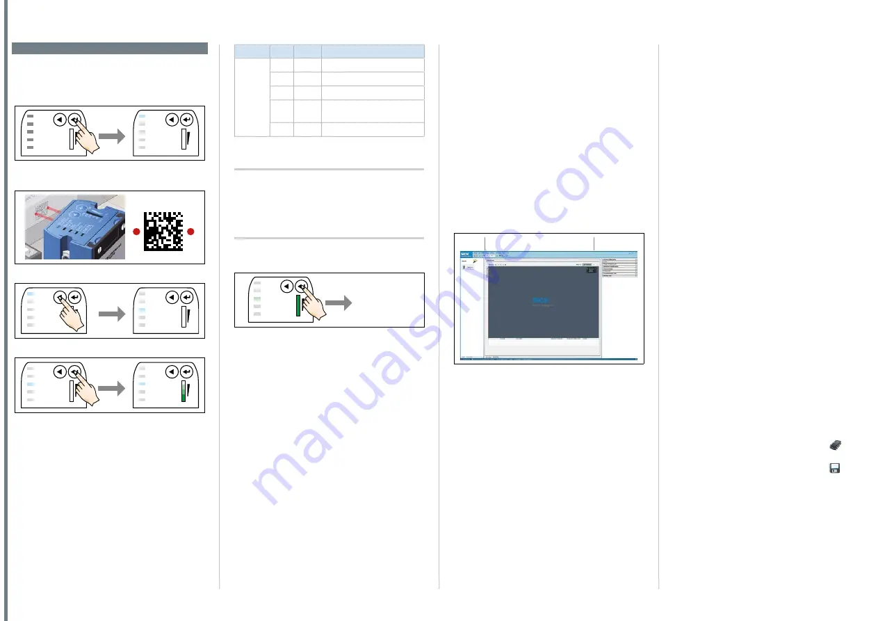
5. Select Lector620 from the list of available de-
vices. SoPAS et establishes communication with
the device and loads the associated device de-
scription file for the device. The program window,
which is divided into three sections, opens.
1
2
3
Fig. 5: SOPAS ET program window: example
1.
“Wizard and help” area
2.
“Image display” area
3.
“Configuration” area
Configuring the device
1. In the
O
nline
i
mage
window, click the
e
dit
button. In
the
e
dit
mode, the device starts recording images
consecutively and uses the current settings to de-
code them. the effects of any parameter changes
become directly visible.
the following functions are deactivated in
e
dit
mode:
• Switching inputs and outputs
• Data output via the host interface.
Configuring reading performance with the Wizard
Configuring with the Wizard is not possible with
pharma codes.
¾
¾
Start the
a
utO
-S
etup
wizard on the left in the
program window and follow the instructions in the
dialog box.
the device adjusts itself automatically with
Auto-Setup to suit the lighting conditions, working
distance, and quality of the code presented. the
device initially temporarily stores these calculated
values. SoPAS et applies the parameters to the
two configuration bars
C
amera
& i
lluminatiOn
and
C
OdeS
.
Continuing the configuration
1. For custom optimization of the image and code
settings of the device, click the
C
amera
& i
llumina
-
tiOn
and
C
OdeS
configuration bars on the right and
adjust the parameter values.
2. to make the changes directly visible, go to the
image display window
O
nline
i
mageS
and click the
e
dit
button.
3. Make settings for additional functions during
planned operation such as codes, reading clock,
read result formats, data interface, etc.
4. Go to the image display window
O
nline
i
mageS
, click
the
O
peratiOn
button, and test the settings in read
mode (real operation).
oCr variant only
¾
¾
For optical oCr/oCV character recognition, start
the oCr Setup wizard on the left of the program
window and follow the instructions in the dialog
box.
Completing the configuration
5. To permanently store the overall configuration:
• Parameter set in the device: Click the
button.
• Configuration file on the PC: Click the
button.


