Chapter
1
Technical Information
HC8X Heat Control
1-16
©
SICK AG · All rights reserved
8010043
Product Description
Note
For the adaptation to the respective heating circuits, the thermally delayed overcurrent
trips installed in the power section have been designed for 4 A, 8 A and 16 A, depending
on the control unit configuration. The use of larger heating circuits is not allowed.
When two- and three-phase heating circuits are connected, the temperature sensors
(PT100) must be assigned to the respective controlling channel (see Chapter 4.5 Con-
figuring the Control Channel as a Follower, page 4-30).
Recommendation
For the external fusing of the power electronics supply voltage (X9), install a three-pole
35 A circuit-breaker (see Chapter 10.2 Electrical Data / Temperatures, page 10-45)
near the HC8X or in the MCS 100 E measuring system cabinet.
For the external fusing of the supply voltage of the control electronics (non-heating ap-
paratus connection), install a single-pole 10 A circuit-breaker (see Chapter 10.2 Elec-
trical Data / Temperatures, page 10-45) near the HC8X or in the MCS 100 E measuring
system cabinet.
1.3
HC8X Process Connection
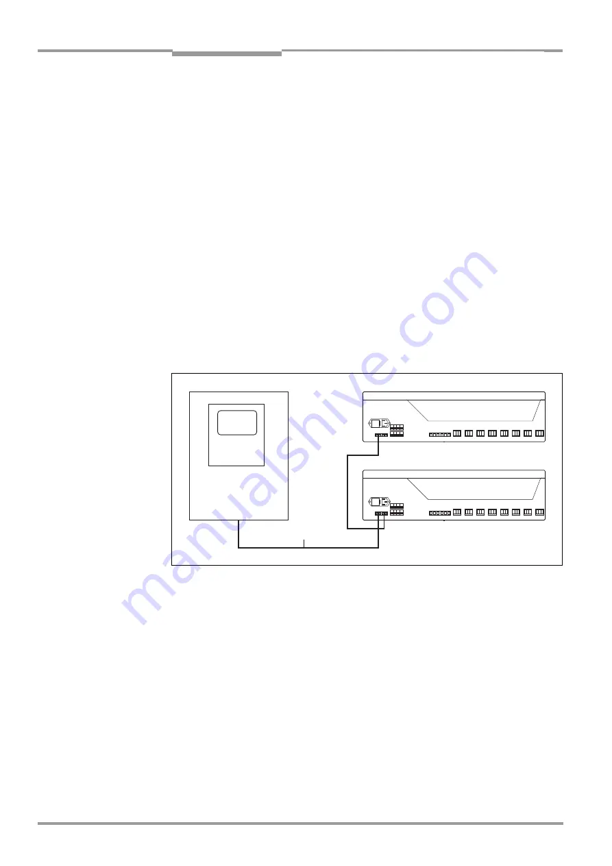
The process connection of the HC8X, e.g. to a MCS 100 E system, is shown in Fig. 3-1.
Fig. 1-3:
HC8X Process Connection
HOST
Optical fiber
MCS 100 E
1.4
Signaling
General LEDs
The LEDs (see Fig. 1-4) indicate the set mode and the states of the individual control chan-
nels.
A green, separate LED (LED 25) signals the HC8X operational state "Idle", "Prog" or
"Norm" and the control channel alarm .
Eight green LEDs (LED 1 – LED 8) signal the states of the individual heating circuits.
Eight red LEDs (LED 9 – LED 16) signal the state of the working relays (HON = Heating
ON, see Chapter 5.4 Control Process, page 5-34).
Eight red LEDs (LED 17 – LED 24) signal the state of the safety relays (HEN = Heating


