background image

MAN-059 


8 FEB 2017 

38 

62.


Attach the pinion shaft nut and washer. Torque to Fuso Canter specifications. 

63.


Ensure the diff rotates freely when the SIBS® brake is released. 

64.


Assemble the drive shaft onto the ABT yoke. 

65.


Apply Loctite 262 to the first five threads of the drive bolts. 

66.


Attach the 4x washers and drive bolts. Torque bolts to 130 Nm. 

67.


Fill the cavity behind the V-lip seal with a high temperature bearing grease (Castrol LMX recommended) via the grease 
nipples located on the yoke. Do not over-grease the V-lip cavity. 

68.


Remove the 4x retractor bolts from the spring cover. 

69.


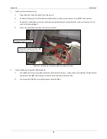
Fit the pad wear indicator to the correct piston: 

a.


Screw the pad wear indicator plunger into the lowest piston thread and torque to 15 Nm. 

b.


Apply Loctite 222 to the gland fitting on the thread that attaches to the spring cover only. 

c.


Fit the gland fitting over the piston and screw this into the spring cover. Torque to 15Nm. 

d.


Fit the stainless steel protective cap and fibre washer to the gland fitting. 

e.


Fit 5x supplied tapered plugs to seal the remaining holes in the spring cover. Use an anti-seize or a low strength 
thread locker on the threads to prevent the plugs seizing in the spring cover. The hex sockets may be filled with 
silicone or similar, to aid future removal. 

70.


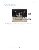
Remove the SIBS® cooling fluid fill plug. 

71.


Fill the SIBS® brake unit with new SIBS® cooling fluid and refit the fill plug with a new copper washer. Approximately 1 
litre of SIBS® cooling fluid is required. 

72.


Check the differential oil level and top up if necessary. 

73.


Inspect all the driveline brake hydraulic hoses and replace as required. 

74.


Replace all rear breather hoses. 

75.


Flush the pump reservoir with new ATF Dexron III and then fill to level window. 

76.


Prime the SIBS® pump by running intermittently (no more than 10 seconds at a time) until full hydraulic pressure is 
reached and the motor stops running automatically. 

a.


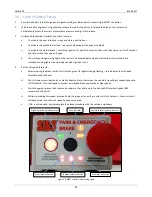
To run the pump and release the EMMA™ brake, twist the red pushbutton on the control unit clockwise.


b.


To release hydrauli

c pressure and engage the EMMA™ brake, press the red operator pushbutton. 


c.


While performing this priming process, ensure the EMMA™ reservoir is constantly topped up to prevent the pump 

from running dry. 

77.


Bleed the driveline brake system as per section 12 paragraph 4 of this manual.  

78.


Conduct a “vehicle pre

-

start check”.


Summary of Contents for Fuso Canter

Page 1: ...SIBS 4 WORKSHOP MANUAL FUSO CANTER...

Page 2: ...draulic sections updated with 24V details Advanced Braking Pty Ltd 2017 All rights reserved No part of this manual may be reproduced in any form or by any means without the prior written consent from...

Page 3: ...ring Diagram 12V 10 8 Wiring Diagram 24V 12 9 Pump Hardware Parts List 12V 14 10 Pump Hardware Parts List 24V 16 11 Installation Driveline Brake Light Medium Trucks 18 12 Installation Hydraulic System...

Page 4: ...rd Canter components While every effort has been made to address all aspects of installation and servicing please advise Advanced Braking of any omissions or suggestions on how this manual may be impr...

Page 5: ...erential Emergency Brake Brakes automatically applied in an emergency EMMA Electronically Modulated Mechanically Applied OEM Original equipment manufacturer Park Brake Brakes applied independently of...

Page 6: ...without affecting operation Important 1 The brake is intended as an emergency brake only for use in the event of a service brake system failure The system is not designed as an additional service brak...

Page 7: ...MAN 059 8 FEB 2017 7 6 Exploded Views Parts Lists Differential Brake Assembly...

Page 8: ...NNECTOR HOSE EMMA 1 20 11 25 2039 PLUG DRAIN 1 20 12 30 2003 WASHER SEALING COPPER 2 13 31 5035 PLUG FILL 1 20 14 31 3001 PIN DOWEL 4 15 21 2001 HOUSING OUTER 1 16 31 2004 WASHER SEALING COPPER 2 17 2...

Page 9: ...EMMA 4 35 31 0002 DISC SPRING 24 36 25 2061 SPRING COVER GASKET 1 37 25 2008 COVER SPRING EMMA 1 38 25 2040 PLUNGER PAD WEAR INDICATOR 1 15 39 25 2041 PLUG PAD WEAR INDICATOR 1 15 40 30 2005 WASHER P...

Page 10: ...MAN 059 8 FEB 2017 10 7 Wiring Diagram 12V TO SPEED SIGNAL TO IGNITION TO OIL PRESSURE TO SEAT BELT 12V...

Page 11: ...MAN 059 8 FEB 2017 11 10A FUSE 30A FUSE 12V POWER...

Page 12: ...MAN 059 8 FEB 2017 12 8 Wiring Diagram 24V TO SPEED SIGNAL TO IGNITION TO OIL PRESSURE TO SEAT BELT...

Page 13: ...MAN 059 8 FEB 2017 13...

Page 14: ...MAN 059 8 FEB 2017 14 9 Pump Hardware Parts List 12V...

Page 15: ...CAP 1 8 18 9029 POWER UNIT GASKET 1 9 18 9030 LEVEL WINDOW 1 10 18 9031 SCREW POWER UNIT 4 11 18 9032 WASHER SPRING POWER UNIT 4 12 18 9033 CABLE GLAND 1 13 18 9034 MANIFOLD BLOCK 1 14 18 9035 RELIEF...

Page 16: ...MAN 059 8 FEB 2017 16 10 Pump Hardware Parts List 24V...

Page 17: ...CAP 1 8 18 9029 POWER UNIT GASKET 1 9 18 9030 LEVEL WINDOW 1 10 18 9031 SCREW POWER UNIT 4 11 18 9032 WASHER SPRING POWER UNIT 4 12 18 9033 CABLE GLAND 1 13 18 9034 MANIFOLD BLOCK 1 14 18 9035 RELIEF...

Page 18: ...al Ensure all shims are reused Do not attach any mounting bolts at this stage 9 Attach the outer bearing roller and pull the pinion shaft forward to ensure it is positioned correctly 10 Attach the pin...

Page 19: ...lose to each other as possible 23 Align the dowel pins before attaching the housing bolts 24 Fit the 12x M10 bolts and torque to 50Nm in sequence Ensure each bolt is torqued twice 25 Attach the 2x gre...

Page 20: ...e washer and cap Torque to 10Nm Figure 4 SIBS Brake assembly attached to rear diff centre 36 Mount the expansion chambers as high as possible in a protected location on the vehicle ABT recommends moun...

Page 21: ...le 2 Drill the pump mounting bracket as required and mount the SIBS pump using provided mounting hardware Figure 7 SIBS 4 pump enclosure 3 Connect one end of the short park emergency brake hydraulic h...

Page 22: ...ne end of the long hydraulic hose to the bulkhead fitting on the inside of the chassis rail 7 Route the other end of the hydraulic hose down along the chassis rail to the brake on the rear diff centre...

Page 23: ...cles the control unit bracket can be reversed so that it is always facing the vehicle operator Figure 11 SIBS 4 control unit mounted on dash 4 Fit the SIBS cabin harness 18 7012 Figure 12 Control unit...

Page 24: ...Push the harness out through an existing rubber boot located at the front of the foot well in front of the passenger seat f Secure the harness where necessary using cable ties g Re pin the connectors...

Page 25: ...the desired length d De pin any unwanted wires from the interface harness Figure 14 Connection for interlocks behind the instrument cluster 6 Fit the OEM door harness 18 7008 optional a The OEM door...

Page 26: ...the battery power extension harness to the battery power harness Figure 15 Battery power harness e Connect the red wires to the positive battery terminal via the eyelet f Connect the black wire to a v...

Page 27: ...0ml approx required b Use ATF Dexron III for the SIBS pump reservoir park emergency system Figure 17 SIBS 4 pump enclosure with lid removed 2 Ensure the battery is in good condition this is critical t...

Page 28: ...the pump reservoir is topped up regularly during the procedure d Once the system is bled apply and then release the park emergency brake again if the system has been sufficiently bled then the brake...

Page 29: ...ock warning lights are only displayed when ignition is on 4 Set the HSI speed threshold a After releasing the brake for the first time the green HSI light will begin flashing this indicates the HSI sp...

Page 30: ...or Service Monthly or every 5 000 km or every 100 hours whichever occurs first Major Service When rear brake pad wear reaches minimum as indicated by the pad wear indicator The pre start check involve...

Page 31: ...warning light should display on control unit d The driver seatbelt is released seatbelt warning light should display on control unit e The engine is stalled low oil pressure warning light should displ...

Page 32: ...Check brake pad wear a Apply the SIBS driveline brake b Remove the protective cap on the pad wear indicator found on the spring cover c The plunger should project out from the gland fitting d The dist...

Page 33: ...nsibly in accordance with regulatory and environmental legislation 12 Refit the drain plug with a new sealing washer 13 Refill the brake up to the level plug fill to spill Approximately 1 litre of SIB...

Page 34: ...12 If the retractor bolts appear to be moving unevenly then check the following a While the brake is releasing the pump is running one or more bolts moves quickly out at the beginning of the pump cyc...

Page 35: ...ner housing ensuring correct orientation 30 Remove the cassette seal from the outer housing and discard 31 Remove the housing o ring from the outer housing and discard 32 If the EMMA springs passed th...

Page 36: ...ed 44 Lubricate all disc springs with a high pressure grease Castrol LMM recommended and reinstall on the park emergency pistons There is 6x springs per piston stacked in series Figure 23 Disc springs...

Page 37: ...n 56 Using a suitable lifting apparatus fit the SIBS brake unit over the pinion shaft 57 Hold the brake rotor to prevent it from detaching from the yoke during assembly 58 Lift outer assembly and alig...

Page 38: ...ng cover Use an anti seize or a low strength thread locker on the threads to prevent the plugs seizing in the spring cover The hex sockets may be filled with silicone or similar to aid future removal...

Page 39: ...bient iv Cycle ignition to clear the fault from the control unit d 5x flashes then rest pump relay fault i Ensure wiring is not causing a short or open circuit to pump relay ii Check pump relay for co...

Page 40: ...ollen preventing them from retracting i Inspect brake for ATF leakage around rear of spring cover ii Strip brake inspect components Replace seals as required c Insufficient hydraulic pressure to relea...

Page 41: ...ores Replace as required 10 Pump does not run SIBS park emergency brake does not release a Check interlocks are not preventing brake release i Close all doors fasten driver s seatbelt start vehicle en...

Reviews: