MAN-059
8 FEB 2017
19
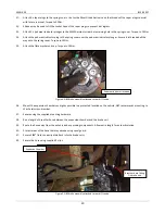
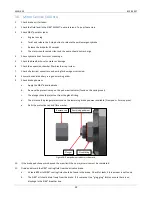
Figure 2: Outer housing, yoke and rotor assembly.
18.
Attach the outer housing, yoke and rotor to the inner brake housing. Use of a jack or lifting table is recommended to
assist with lifting the assembly into position.
19.
Hold the brake rotor to prevent it from detaching from the yoke during assembly.
20.
Lift outer assembly and align the yoke with the pinion shaft with the EMMA spring covers positioned towards the bottom
of the brake.
21.
Once the brake is held by the pinion shaft, rotate the outer housing until the EMMA spring covers are positioned towards
the top of the brake.
22.
Remove any rotor retaining devices once the inner and outer housings are as close to each other as possible.
23.
Align the dowel pins before attaching the housing bolts.
24.
Fit the 12x M10 bolts and torque to 50Nm in sequence. Ensure each bolt is torqued twice.
25.
Attach the 2x grease nipples to the yoke.
26.
Attach the pinion shaft nut. Set preload and torque as per Fuso Canter Manual.
27.
Ensure the diff rotates freely when the SIBS® brake is released.
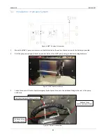
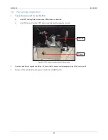
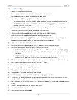
Figure 3: Brake mounted in position on the forward side of the rear diff centre.
28.
Assemble the drive shaft onto the ABT yoke. Torque fasteners to 130Nm.
29.
Complete the hydraulic and electrical installations as per sections 10 and 11 of this manual.
30.
Remove the 4 x retractor bolts from the brake and retain in the vehicle.
Ensure Brake Pads are in position
before attaching rotor (not shown)
EMMA Spring cover
EMMA Spring cover centred
at the top of the brake
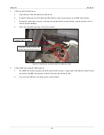
M10 Housing bolts located
on the rear facing side
Summary of Contents for Fuso Canter
Page 1: ...SIBS 4 WORKSHOP MANUAL FUSO CANTER...
Page 7: ...MAN 059 8 FEB 2017 7 6 Exploded Views Parts Lists Differential Brake Assembly...
Page 11: ...MAN 059 8 FEB 2017 11 10A FUSE 30A FUSE 12V POWER...
Page 13: ...MAN 059 8 FEB 2017 13...
Page 14: ...MAN 059 8 FEB 2017 14 9 Pump Hardware Parts List 12V...
Page 16: ...MAN 059 8 FEB 2017 16 10 Pump Hardware Parts List 24V...


