Rudder Feedback / GPS Wiring Diagrams
Pin connections from rear of plug, solder connection side.
Pin 1 has adjacent dot. See Figure 6.
Pin 1
5V Rudder Feedback Supply
Pin 2
Rudder Feedback Wiper Return
Pin 3
0V Rudder Feedback Supply
Pin 4
TX Data (heading information)
Pin 5
+ GPS Input (Positive)
Pin 6
- GPS Input (Negative)
Figure 6: Pin Assignments
SP-110C View
GPS Wiring Connections
Pin connections from rear of plug, solder connection side.
Pin 5 + GPS Input (Positive) - white wire
Pin 6 - GPS Input (Return) - green wire
For GPS navigation, connect the GPS unit via the two wires coming from
the back of the rudder feedback plug on the SP-110C display unit.
Heading Data out is also available
Pin 4 + Heading Data Out (Positive) - red wire
Pin 3 - Heading Data Out (Negative) - blue wire (0 volt line)
8 of 35
SI-TEX SP-110C
Note: For information on connecting different
brands of GPS units, refer to the relevant GPS manual
Note: Pin locations are relative to pin 1 which
always has a dot adjacent.
Summary of Contents for SP-110C
Page 1: ...SP 110C Autopilot USER MANUAL IMPORTANT PLEASE RETAIN ONBOARD ...
Page 2: ... This page intentionally left blank ...
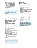
Page 9: ...6 of 35 SI TEX SP 110C ...
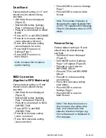
Page 21: ...SI TEX SP 110C 17 of 35 ...
Page 42: ......


