- 11 -
3 HARDWARE INSTALLATION
Before removing or installing any of these devices including CPU, DIMMs,
Add-On Cards, Cables, please make sure to unplug the onboard power
connector.
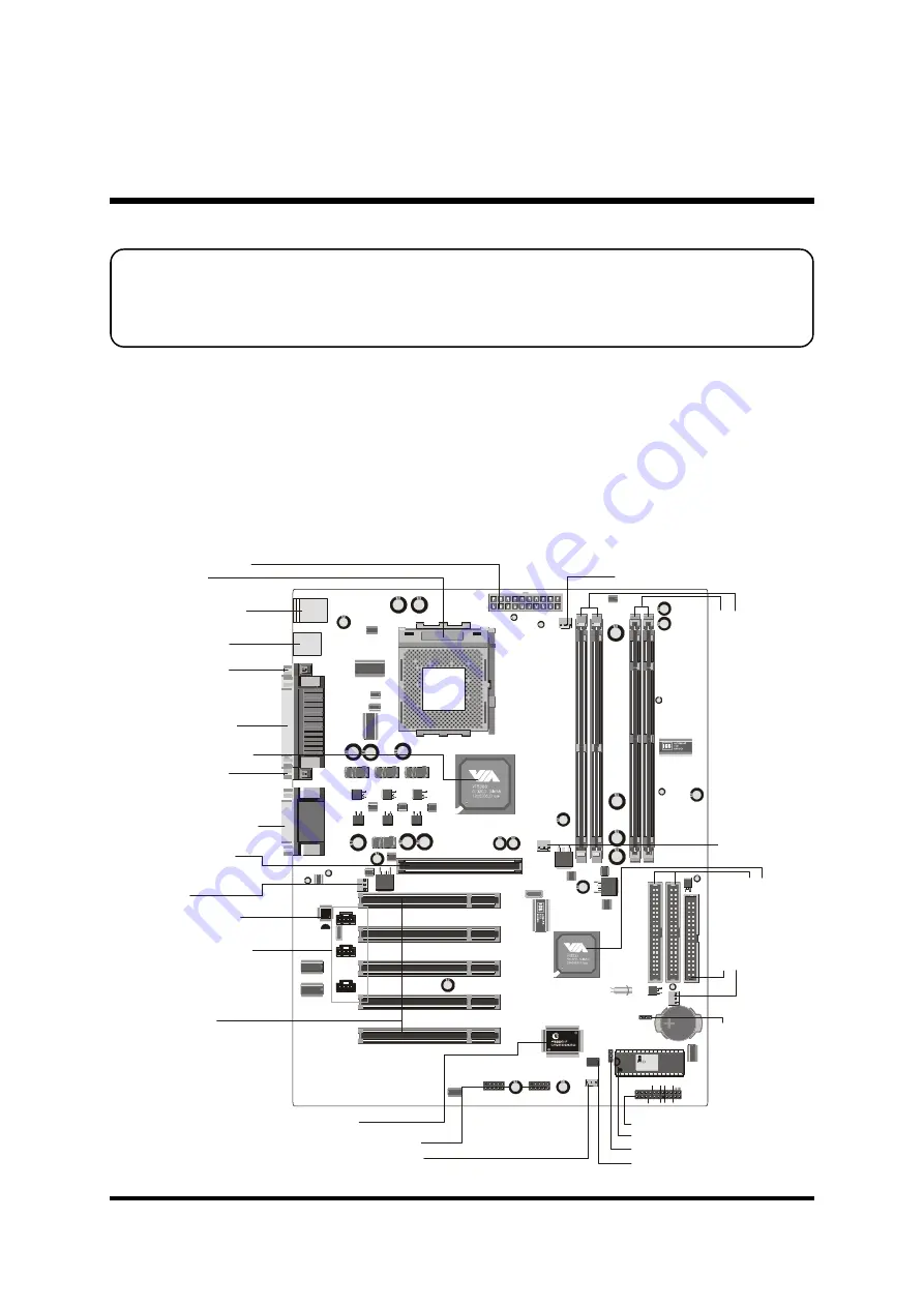
This section outlines how to install and configure your AK32E mainboard. Refer to the
following mainboard layout to help you identify various jumpers, connectors, slots, and
ports. Then follow these steps to guide you through a quick and correct installation of
your system.
3.1 Step-by-Step Installation
Accessories Of AK32E
KB1
USB1
CON1
AGP_FAN
SYSTEM_FAN
AUDIO1
IDE2
CPU_FAN
NB_FAN
IDE1
FDD
WOL
PCI1
PCI2
PCI3
PCI4
PCI5
IR
USB5&6
USB3&4
P
an
as
on
ic
C
R2
03
2
3V
JA
P
A
N
1
CN4
CN3
CN2
TAD/IO
CD-IN
AUX
AGP1
1
1
1
10
10
1
1
1
1
1
1
1
1
1
JP16
JP2
JP5
JP4
JP3
FAN3
FA
N2
FAN1
FA
N4
FD
D1
ID
E2
ID
E1
1
1
1
AWARD
PCI/PNP 686
169332966
1998
C
CN1
1
inbond
DIMM1
DIM1
JP6
DIMM2
DIM2
SO
CK
ET
46
2
PS/2 Keyboard/Mouse
Connectors
ATX Power Connector
Parallel Connector
Serial Port
Connector (COM2)
Serial Port
Connector (COM1)
Line-In/Line-Out/Mic-In
Game/MIDI Connectors
Fl
op
py
C
on
ne
ct
or
BIOS Write Protection - JP3
Front Panel Connector - JP7
Tw
o
E-
ID
E
C
on
ne
ct
or
s
F
A
N
3
FAN1
F
A
N
4
FAN2
Socket462
Five PCI Slots
One 4 X AGP Slot
VIA VT8366A Chipset
V
IA
V
T8
23
5
C
hi
ps
et
USB Connectors
IR Connector - JP2
C
le
ar
C
M
O
S
- J
P1
6
I/O Controller
CD Audio Connectors
Onboard CODEC
Wake-On-LAN Connector - CN1
Programmable 2Mb Flash EEPROM
Extended four USB Connectors
header - JP4/JP5
Tw
o
18
4-
pi
n
D
D
R
D
IM
M
S
lo
ts
Tw
o
16
8-
pi
n
SD
R
D
IM
M
S
lo
ts
PWR1 ATXPWR
JP7
1
RST
Power LED
- +
SPEAKER
GLED
+ -
- +
EPMI
Power
On


