Shure Incorporated
21/75
4.
5.
Use the included cable clamp to secure the cables in place.
Turn on the CCU by pressing the power button. The conference units will power on. The unit is stable once the control
button LEDs stop flashing.
Warning:
Do not turn off CCU power until the system has stabilized
Connection Diagrams
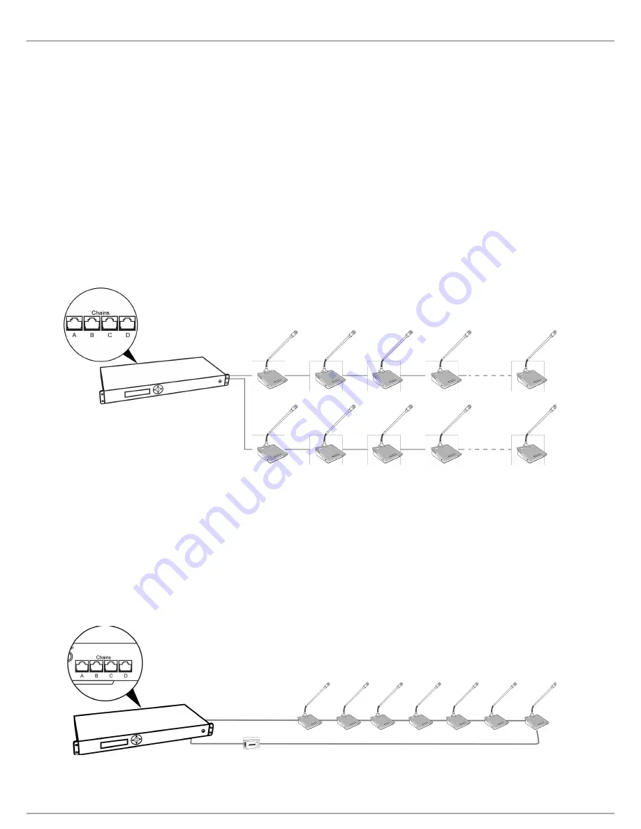
The following system diagrams illustrate typical hardware connections to the CCU. Actual installations may use different combi-
nations of hardware, but follow the general concepts outlined below.
Note:
Flush-mount and portable conference units are interchangeable in the following drawings, unless noted.
Basic Setup with Conference Units
The system is operational without the use of a computer. Use the CCU navigation screen to change the speak operation set-
ting if needed. Use the CCU web interface if advanced setup options are needed.
Basic System with Multiple Chains
Redundancy
The system is operational without the use of a computer. Use the CCU navigation screen to set up the installation.
Cable redundancy in an MXC system can be achieved by connecting the DCS-LAN OUT port of the last MXC conference unit
to an MXC Redundancy Interface Box (MXC-ACC-RIB), and looping back to a DCS-LAN port on the CCU.
Note:
Systems including legacy DIS units do not support cable redundancy.
Basic System with Redundant Cabling


