background image

Locking the Receiver Controls

Simultaneously press and hold the group and channel buttons until

LK

ap-

pears on the LCD. Repeat to unlock.

LK

is displayed if a locked control is pressed

UN

is displayed momentarily to confirm the unlock command

Locking the Transmitter Power Switch

Starting with the transmitter set to

off

, press and hold the

LINK

button while

turning on the transmitter. Continue to hold the link button until the lock icon
appears on the receiver LCD. Repeat sequence to unlock.

Optionally, the transmitter power switch can be remotely locked from the re-
ceiver front panel:

Simultaneously press and hold the

group

and

link

buttons for approximately

2 seconds until the flashing lock icon appears on the receiver LCD. Repeat
sequence to unlock.

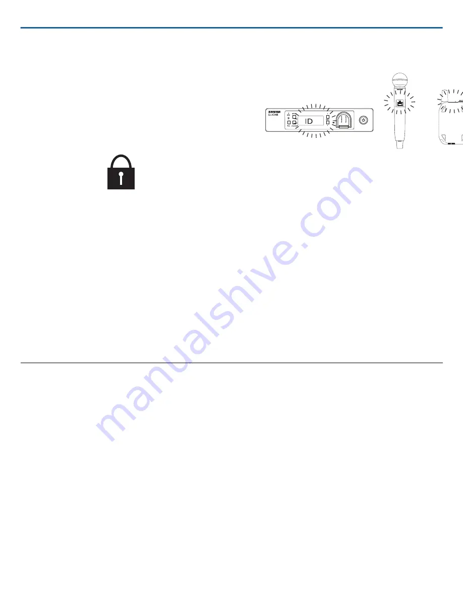
Identifying Linked Transmitters and Receivers with
Remote ID

Use the Remote ID feature to identify linked transmitter and receiver pairs
in multiple receiver systems. When Remote ID is active, the receiver LCD
will blink and display

ID

. The status LED of the corresponding transmitter will

alternately flash red and green for approximately 45 seconds.

To activate Remote ID:

1. Momentarily press the

link

button on the transmitter or receiver.

2. The LCD of the linked receiver will blink and display

ID

and the status

LED on the linked transmitter will flash red/green.

3. To exit Remote ID mode, momentarily press the

link

button or allow the

function to timeout.

Manually Selecting a Group and Channel

Specific groups and channels can be assigned to the receiver instead of using
the automatic scan function.

Note:

Group 3 should only be used in controlled Wi-Fi environments to pre-

vent interference from unexpected Wi-Fi devices.

Selecting a Group

1. Press and hold the

group

button for 2 seconds until the

group

display

flashes.

2. Press the

group

button to scroll through the available groups.

3. The receiver will automatically save the selected group.

Selecting a Channel

1. Press and hold the

channel

button for 2 seconds until the

channel

display

flashes.

2. Press the

channel

button to scroll through the available channels.

3. The receiver will automatically save the selected channel.

Note:

A double dash symbol

--

displayed on the receiver screen during a

channel scan indicates that there are no available channels within the selected
group. Choose a group with more channels and repeat set up steps.

Firmware

Firmware is embedded software in each component that controls functionality. Periodically, new versions of firmware are developed to incorporate additional
features and enhancements. To take advantage of design improvements, new versions of the firmware can be downloaded and installed using the Shure Update
Utility tool.

Software is available for download from

http://www.shure.com/update-utility

.

Connect to the Computer

Connect the device to your computer using the USB to Micro USB cable supplied with your GLX-D system.

Shure Incorporated

GLXD4R

 Half-Rack Wireless Receiver

13/20

2017/11/28

Summary of Contents for GLXD14R

Page 1: ...to a MAINS socket outlet with a protective earthing connection 19 To reduce the risk of fire or electric shock do not expose this apparatus to rain or moisture 20 Do not attempt to modify this product...

Page 2: ...gnal Automatically moves away from interference without audio interruption RF back channel for remote control of transmitter functions Automatic transmitter power off to conserve battery life when tra...

Page 3: ...plifier or mixer Step Install charged transmitter batteries Step Turn on the transmitter and receiver The blue rf LED will flash while the transmitter and receiver form a link The rf LED turns solid b...

Page 4: ...usage At power up the blue rf LED and transmitter LED will illuminate skipping the linking step Step Check the audio and adjust the gain if necessary Receiver Controls and Connectors Front Panel Shure...

Page 5: ...Press to start a channel scan Press and hold for two seconds to enable manual channel edit LCD Screen Displays receiver and transmitter status Gain Buttons Press to increase or decrease transmitter g...

Page 6: ...ing battery life in hours and minutes Alternatively displays the following battery status CALC battery life calculation Lo battery life less than 15 minutes Err replace battery Audio Meter Indicates a...

Page 7: ...transmitter searching for receiver Flashing fast indicates locked transmitter when power switch is pressed Flashes 3 times battery life 1 hour On Red battery life 30 minutes Flashing remote ID active...

Page 8: ...is plugged in to power outlet 1 Insert the battery into the charging bay 2 Monitor the battery charging indicator on the front panel Charging from an AC Power Source 1 Plug the charging cable into the...

Page 9: ...ntime Note If receiver is powered off and remains plugged in battery will continue charging Important Tips for Care and Storage of Shure Rechargeable Batteries Proper care and storage of Shure batteri...

Page 10: ...nnas remotely using Shure directional antennas to reduce transmitter to antenna distance Challenging environments include Areas with few reflective surfaces such as Outdoors Buildings with very high c...

Page 11: ...ther from each other to improve performance Position antennas so there is nothing obstructing the line of sight to the transmitter including the audience Keep antennas away from metal objects and any...

Page 12: ...on the transmitter Within 5 seconds press and hold the LINK button until the transmitter LED begins to flash green 2 Press and hold the link button on the receiver The blue rf LED will flash and then...

Page 13: ...button or allow the function to timeout Manually Selecting a Group and Channel Specific groups and channels can be assigned to the receiver instead of using the automatic scan function Note Group 3 sh...

Page 14: ...Rack Mounting Instructions Use the supplied mounting hardware to install the receiver in a standard 19 inch audio equipment rack Shure Incorporated GLXD4R Half Rack Wireless Receiver 2017 11 28 14 20...

Page 15: ...Shure Incorporated GLXD4R Half Rack Wireless Receiver 15 20 2017 11 28...

Page 16: ...rent group and or channel Identify nearby sources of interference cell phones Wi Fi access points signal pro cessor etc and shut down or remove source Charge or change transmitter battery Ensure that...

Page 17: ...es behind antennas in the null to minimize interference Place receivers or directional antennas closer to transmitters Receiver screen flashes RF interference while connected to frequency manager Rese...

Page 18: ...without batteries Power Requirements 3 7 V Rechargeable Li Ion Housing Cast Metal Black Powdercoat Input Impedance 900 k RF Output Power 10 mW E I R P max Transmitter Input Connector 4 Pin male mini...

Page 19: ...m 1 4 output Full Scale Output 12 dBV 1 4 6 35 mm LINE setting 18 dBV MIC setting 12 dBV XLR Mic Line Switch 30 dB pad Pin Assignments 1 ground 2 hot 3 cold XLR Output Tip audio Ring no audio Sleeve g...

Page 20: ...ure Europe GmbH Headquarters Europe Middle East Africa Department EMEA Approval Jakob Dieffenbacher Str 12 75031 Eppingen Germany Phone 49 7262 92 49 0 Fax 49 7262 92 49 11 4 Email EMEAsupport shure d...

Reviews: