


Notes
Number of Backup
Frequencies Per Channel
Channel Count (Number of
Receivers)
Group
Only use Group 3 in controlled Wi-Fi environments because there are no backup
frequencies to avoid interference.
0
Up to 8*
3
Best
single-channel
group if you experience interference.
27
1
4
*Environmentally dependent, 4 systems typical
See "Tips to Improve Wireless System Performance" section for additional information. For information about receiver groups when connected to the GLX-D
Frequency Manager, see the UA846 user guide.
Setting Up Receivers and Transmitters
Note:
Before beginning, turn off all receivers and transmitters. Turn on and set up each receiver/transmitter pair individually to prevent cross-linking.
1. Turn on the first receiver.
2. Press and hold the
group
button to select a group (if necessary) or if the group is already set, press the
channel
button to scan for the best available channel.
3. Turn on the first transmitter. The
rf
LED turns solid blue when a link is established.
Repeat steps 1-3 for each additional receiver and transmitter. Remember to set each receiver to the same group.
See GLX-D Frequency Manager guide for setting up receivers and transmitters when connected to the frequency manager.
Note:
Dashes appearing on the group and channel display during a channel scan indicate that frequencies are not available in the selected group. Choose a
group that supports more receivers and repeat set-up steps.
Manually Linking a Transmitter to a Receiver
Use the manual linking option to change the transmitter linked to a receiver.
A common use for manual linking is changing the linked transmitter from a
bodypack type to a handheld type.
1. Turn on the transmitter: Within 5 seconds, press and hold the
LINK
button
until the transmitter LED begins to flash green.
2. Press and hold the link button on the receiver: The blue
rf
LED will flash,
and then remain on when the link has been established.
3. Test the audio to verify the link and adjust the gain if necessary.
Combo Systems
A combo system is created by linking two transmitters to a single receiver.
Only one transmitter can be active at a time to prevent cross interference.
Gain settings for each transmitter can be independently set and stored when
the transmitter is active.
Important!
Do not turn on and operate both linked transmitters at any time.
Turn off both transmitters before beginning.
1. Press the
group
button to select a group. The receiver automatically
scans the selected group to find the best available channel.
2. Turn on transmitter 1 and link it to the receiver. Adjust the gain, and then
turn off the transmitter.
3. Turn on transmitter 2 and link it to the receiver. Adjust the gain, and then
turn off the transmitter.
Note:
A transmitter can only link to one GLX-D receiver at a time.
Operation
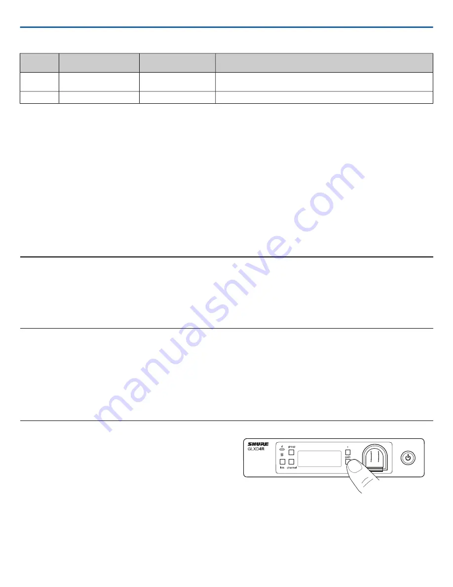
Gain Adjustment
Use the gain buttons on the receiver to increase or decrease the gain of a
linked transmitter:
•
Turn on the linked transmitter and momentarily press the gain buttons
to adjust the gain in 1 dB increments
•
For faster gain adjustments, press and hold the gain buttons
•
To replicate the output level of a guitar, unity gain is -18 dB for the ¼"
output
Tip:
Monitor the audio and observe the receiver audio meter level while ad-
justing the gain to prevent signal overload.
Locking and Unlocking the Controls
The controls of the receiver and transmitter can be locked to prevent acciden-
tal or unauthorized changes to settings.
Note:
Locks are not affected by power cycles.
Shure Incorporated
GLXD4R
Half-Rack Wireless Receiver
2017/11/28
12/20


