Shure Geobox G-302 Quick User Manual Download Page 9

G-302 Quick User Manual                                                                                                              Document: G-302101 

------------------------------------------------------------------------------------------------------------------------------------------------ 


Limitation in adjustment range: The adjustment range in the corner will be varied in different output 

resolution from GeoBox. For output resolution under 1400x1050, the range will be ±256 pixels in 

horizontal and ±200 in vertical direction. For XGA resolution, the adjustment range is about 9.5 grids in 

horizontal and 7.5 grids in vertical directions. At full HD output, the range will be ±200 (4 grids) in 

horizontal and ±100 pixels (2 grids) in vertical directions. 


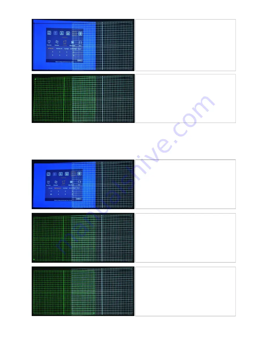
3.  Start [4 Corner] adjustment in another channel (CH-A) 

1.  Activate [4 Corner] key in one channel (figure in 

CH-B). An indicator (CHANNEL B) will be showed 
at the bottom right of the OSD. 

2.  Select the corner for the adjustment and press 

[OK] to enter 4 corner adjustment in CH-B 

3.  If user wants to start from CH-A, please press [CH 

A/B] key to switch to CH-A. If no grid pattern 
appears, please press [Pattern] key again. 

1.  A green Mark at the corner (Top Left) to show the 

corner to be adjusted. 

2.  Using OSD direction keys to move the corner 

position into screen border. 

1.  Press [OK] key will activate [4 Corner] menu again 
2.  Select next image corner to be adjusted (Bottom 

Left is selected in left figure). 

3.  A green Mark is showed at the corner to be 

adjusted. 

1.  To move [Bottom Left] corner into the screen 

border. 

2.  A green Mark in bottom left showed the   

adjustment result 

Apply the same procedures as above to adjust [Top 
Right] and [Bottom Right] corner of the image and let 
the image of CH-B become rectangular inside the 
screen borders.   

Summary of Contents for Geobox G-302

Page 1: ...r passive 3D display 10 User friendly OSD and IR remote control No PC is required 11 IR extender RS 232 control 12 Allow same setup for 3D display and high brightness 2D stacking 13 Support curved scr...

Page 2: ...s due to input timing change and HDCP validation GeoBox will automatically connect to input source Then the screen will show up with double images To set HDMI as projector input may reduce the time fo...

Page 3: ...ner key to show 4 Corner OSD menu in one channel and another channel still retains grid pattern 2 Select the corner to be adjusted by OSD direction keys 3 While full HD output from GeoBox grid pattern...

Page 4: ...r menu again in CH A 2 Select the second corner to be adjusted 3 Press OK key then it will show Red Mark at the selected corner 4 To adjust the position of the corner to match the screen border by dir...

Page 5: ...gnal is standard HDMI 1 4 3D formats from Blue Ray player 3 Select other items based on user s 3D input formats 2D to 3D conversion side by side SBS or top bottom T B formats 1 If 2D to 3D format is s...

Page 6: ...ent In this case system will restart within one minute User can also turn OFF ON the system to restart again This kind of situation will not happen once the complete system setup is finished It will n...

Page 7: ...e same To put temporary marks on the screen to indicate the final location of the images and align the images to meet the required size An Excel Spread Sheet can be provided for the calculation of the...

Page 8: ...menu will split the input image crop the right image area and assign to each projector to finish the complete Edge Blending procedures 6 Image fine tune After the above procedures it is possible to ha...

Page 9: ...ttom right of the OSD 2 Select the corner for the adjustment and press OK to enter 4 corner adjustment in CH B 3 If user wants to start from CH A please press CH A B key to switch to CH A If no grid p...

Page 10: ...rn with a Mark at the corner to be adjusted 2 To move the image into screen border and follow the same procedures to adjust all corner at CH A Left figure shows both CH A CH B corners had been adjuste...

Page 11: ...ls edge blending shall be applied D To extend the image into two projectors Before Enable extend function After Enable extend function E To fine tune Overlap value under Edge Blend menu 1 Overlap valu...

Page 12: ...G 302 will have different values although it show the same number of overlap grid pattern c Activate Overlap OSD under Edge Blend menu and check the value settings in both CH A CH B then increase or...

Page 13: ...on or lens shift function inside the projector then to use 4 Corner adjustment to align the images from the 2nd and 3rd projectors onto the first one 6 For curved screen stacking only two projectors c...

Page 14: ...er adjustment ranges and reduce the loss of the image resolution and brightness Please make sure ventilation hot air will not affect each other 2 Maximum 4 Corner adjustment range in each corner is 25...

Page 15: ...of revenue inconvenience or interruption in operation experienced by the customer Warranty service shall not automatically extend the warranty period Technical support Steve Wang Tel 886 2 8751 2785 e...

Reviews: